
1. Source, Authority and Numerical Boundaries
This is ProMagTech's independent engineering commentary on Infineon's public REF_12KW_HFHD_PSU reference design. Infineon's current evaluation-board page lists 12 kW output, 113 W/in³ power density, 97.5% peak efficiency at 230 VAC including fan power, and 96.5% efficiency at full load. These are Infineon reference-design values, not ProMagTech product measurements.
Official Infineon evaluation-board page · Official Infineon application note
2. Two Series-Primary, Parallel-Secondary Transformers
The reference design uses two identical 9:2 hybrid planar transformers with series primaries and parallel secondaries. The intent is to divide unit voltage and secondary current while improving sharing conditions. Current sharing is not automatic under every tolerance; turns ratio, interconnect resistance, temperature and synchronous-rectifier timing still need prototype validation.
3. Magnetizing Inductance Is Separated From Power Transfer
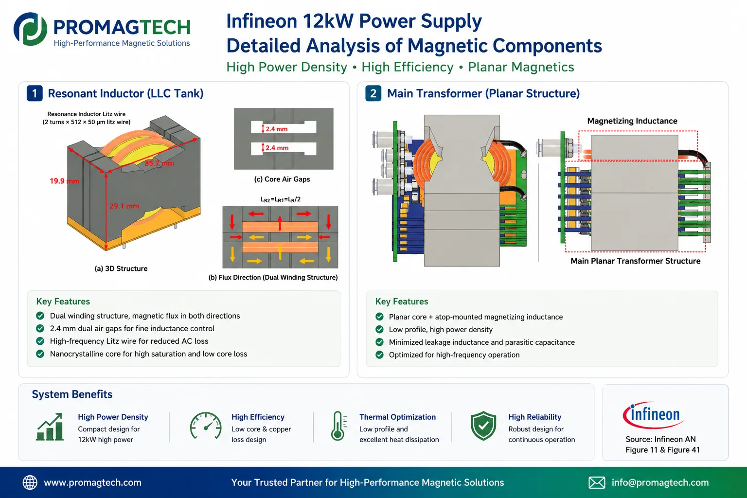
The main magnetic path uses a very small gap, while a separate top winding and larger gap set the magnetizing current needed for ZVS. This decouples part of the power-transfer geometry from the magnetizing-current requirement, but it makes fringing-flux management around the gap critical for avoiding local Litz-wire heating.
4. PCB Windings, Synchronous Rectification and Cooling Are Co-Designed
A 5-turn board and a 4-turn board form the 9-turn primary, with multiple boards paralleled to reduce AC resistance. Secondary winding boards integrate synchronous-rectifier devices to shorten the commutation loop. The source presents extra copper layers as heat spreaders and shows a simulated hot-spot change from 96.1 °C to 87.3 °C. That comparison is simulation, not a finished-system temperature-rise test.
5. The External Resonant Inductor Cancels Flux in Its Center Section
The 1.65 µH resonant inductor is divided into two magnetic chambers with winding directions selected to cancel flux in the center I-piece. The concept can reduce a local core-loss concentration, but production feasibility still depends on gap tolerance, winding consistency, acoustic behavior and full-load thermal validation.
6. PFC and EMI Magnetics Serve the System Layout
| Magnetic | Public reference-design direction | Project validation |
|---|---|---|
| PFC boost inductor | Distributed-gap powder-core toroid to retain inductance under DC bias and contain stray flux | L-I curve, copper/core loss, sensor error, chassis eddy current and temperature rise at the operating point |
| Energy-buffer inductor | Designed around hold-up and grid-shaping events rather than only continuous full load | Event duration, repetition, peak current, accumulated heat and life |
| Dual-stage CM chokes | Magnetic shunts create controlled leakage for integrated DM inductance; 0.6 × 5 mm flat-wire windings carry input current | CM/DM impedance, shunt assembly tolerance, insulation, temperature rise and system EMI |
7. What Manufacturing Must Actually Prove
Parallel PCB stacks, embedded SR devices, thin insulation layers, FR4 spacing, Litz-to-gap distance, magnetic-shunt insertion and flat-wire forming are process-capability questions. Before production, the DVP should control dimensions, L/Lr/Lm, DCR and AC loss, hipot, partial discharge, temperature rise and lot-to-lot consistency rather than copying the visible geometry alone.
8. Frequently Asked Questions
Which performance values should be used for the Infineon reference design?
Infineon's current evaluation-board page lists 12 kW output, 113 W/in³ power density, 97.5% peak efficiency at 230 VAC including fan power, and 96.5% efficiency at full load. If a secondary commentary gives a different value, use the current Infineon source and its revision as the authority.
Why does the LLC stage use two transformers instead of one?
The public reference design uses two 9:2 transformer units with series primaries and parallel secondaries. This divides voltage and secondary current between units and supports current sharing, but final sharing, losses and tolerances still require prototype measurement.
Why is magnetizing inductance implemented as an external top winding?
The source design keeps the main transformer gap very small and adds a separate top-mounted winding and gap to set magnetizing current for ZVS. This separates power-transfer geometry from the magnetizing-current requirement, while making fringing-flux control around the gap essential.
Is the reported 96.1 °C to 87.3 °C hot-spot reduction a measured result?
No. The source material presents it as a thermal-simulation comparison under matched loss and airflow assumptions. It is useful for design direction but must not be presented as a finished-product temperature-rise test.
Why are powder-core toroids used for the PFC inductors?
The distributed-gap toroidal structure helps contain stray flux around nearby current sensors and the metal chassis while retaining inductance under DC bias. Core material, turns, wire and thermal performance remain operating-point specific.
Can ProMagTech claim identical performance from this analysis?
No. This article explains a public Infineon reference architecture; it is not a ProMagTech test report, endorsement or equivalent-design guarantee. Any proposed transformer, resonant inductor, PFC inductor or EMI choke requires project inputs, design review and sample validation.
Download the English PDF Reference
Eight-page English technical commentary, PMT-RPT-2026-0806-02, Rev A/1, dated 2026-08-06.
Download PDF Data