
1. What This Reference Does
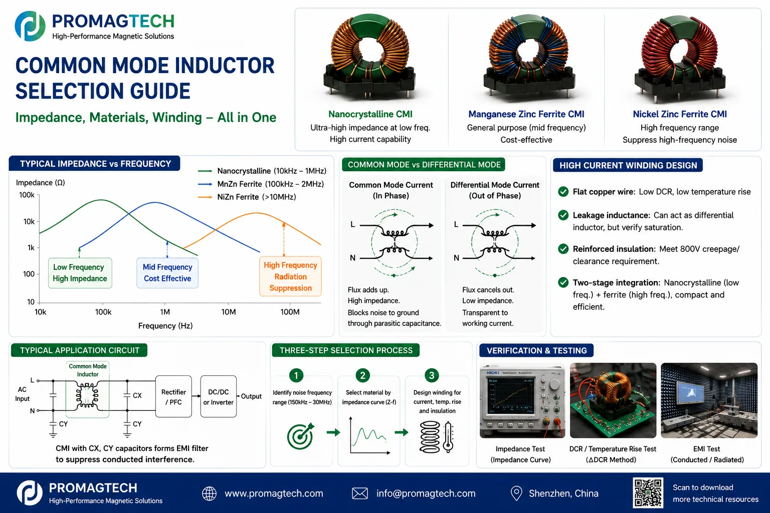
A common-mode choke inserts high impedance into the common-mode noise path while remaining nearly transparent to differential working current. Selection should start with the failing frequency band, continue through measured impedance-frequency curves and material choice, and finish with current, rise, insulation and system-level EMI validation.
2. Separate Common-Mode and Differential-Mode Noise
| Dimension | Common mode (CM) | Differential mode (DM) |
|---|---|---|
| Path | Both lines in phase, returning through ground parasitics | Out on one line and back on the other |
| Main source | Switch-node dv/dt coupling | Switching-current ripple |
| Typical fix | CM choke plus Y capacitors | DM inductor plus X capacitors |
| Typical band | Hundreds of kHz to 30 MHz and above | 150 kHz to a few MHz |
3. Select Core Material from the Impedance Curve
| Material | Typical strong band | Main traits | Typical use |
|---|---|---|---|
| Nanocrystalline | 10 kHz-1 MHz | Very high permeability, few turns, compact, high Bsat | EV OBC and PV/ESS high-current CM |
| MnZn ferrite | 100 kHz-2 MHz | Economical and widely sourced | General SMPS input filters |
| NiZn ferrite | >10 MHz | Strong high-frequency impedance | High-frequency fill-in and radiated fixes |
| Amorphous | 10 kHz-500 kHz | Strong low-band route with different cost tradeoffs | Industrial supplies |
High-frequency impedance collapse is often caused by resonance between inter-turn parasitic capacitance and common-mode inductance. Sectioned windings, fewer turns or an added high-frequency stage may outperform a simple material change.
4. High-Current Windings, Leakage and Two-Stage Integration
Flat wire: reduces DCR and supports lower rise at high through-current. Leakage: can provide differential-mode filtering, but saturation and local heating must be checked at worst-case current. Insulation: high-voltage designs require project-specific creepage, clearance and reinforced-insulation review. Two-stage integration: can combine a low-frequency nanocrystalline stage and a high-frequency ferrite stage in one compact structure, subject to system validation.
5. Application and Validation Baseline
General SMPS designs often prioritize impedance coverage and cost. EV OBC, PV inverters and ESS PCS add high through-current, rise, insulation and outdoor boundaries. Datacenter power also emphasizes low profile and density. A DVP should cover the CM impedance curve, CM inductance, leakage, DCR and rise, hi-pot, impedance under current, system EMI scans and batch consistency.
6. Frequently Asked Questions
Why does load current not saturate a common-mode choke?
The two windings carry differential working current with opposing magnetic fluxes, so their net core flux is close to zero. Common-mode current and leakage flux do not cancel, so leakage saturation still requires review at high current.
Should I choose nanocrystalline or ferrite?
Choose by frequency band and current. Nanocrystalline supports strong low-band impedance and compact high-current designs; MnZn ferrite is economical in the mid band; NiZn is commonly used as a high-frequency fill-in above 10 MHz. Final selection follows measured Z-f curves.
Why does common-mode impedance collapse at high frequency?
Inter-turn parasitic capacitance resonates with common-mode inductance. Above resonance the device becomes increasingly capacitive. Sectioned windings, fewer turns or a second high-frequency stage can be more effective than simply changing core material.
What is the tradeoff when leakage inductance is used for differential-mode filtering?
It can save a separate differential-mode inductor, but leakage flux follows the load current and can saturate, heat locally and increase radiation. Verify leakage inductance, saturation and temperature rise at the worst operating current.
Can common-mode chokes produce audible noise?
Yes. Audio-band common-mode current can excite magnetostriction. Material and process selection, varnish or potting, mechanical restraint and control strategies that avoid sensitive audio bands can reduce noise.
What should be checked if component parameters pass but the system still fails EMI?
Review the complete noise path. Y-capacitor placement, grounding, layout parasitics and shielding can dominate. Work backward from the failing band before deciding whether the choke, capacitor network or layout must change.
What common-mode magnetics can ProMagTech review?
ProMagTech can review MnZn and nanocrystalline chokes, high-current flat-wire common-mode chokes and two-stage integrated structures, with a project-specific DVP covering impedance curves, leakage, temperature rise and impedance under current. Final scope depends on the submitted system conditions.
Download the English PDF Reference
Six-page English engineering reference, PMT-DOC-2026-0726-08, Rev A/0, dated 2026-07-26.
Download PDF Data