
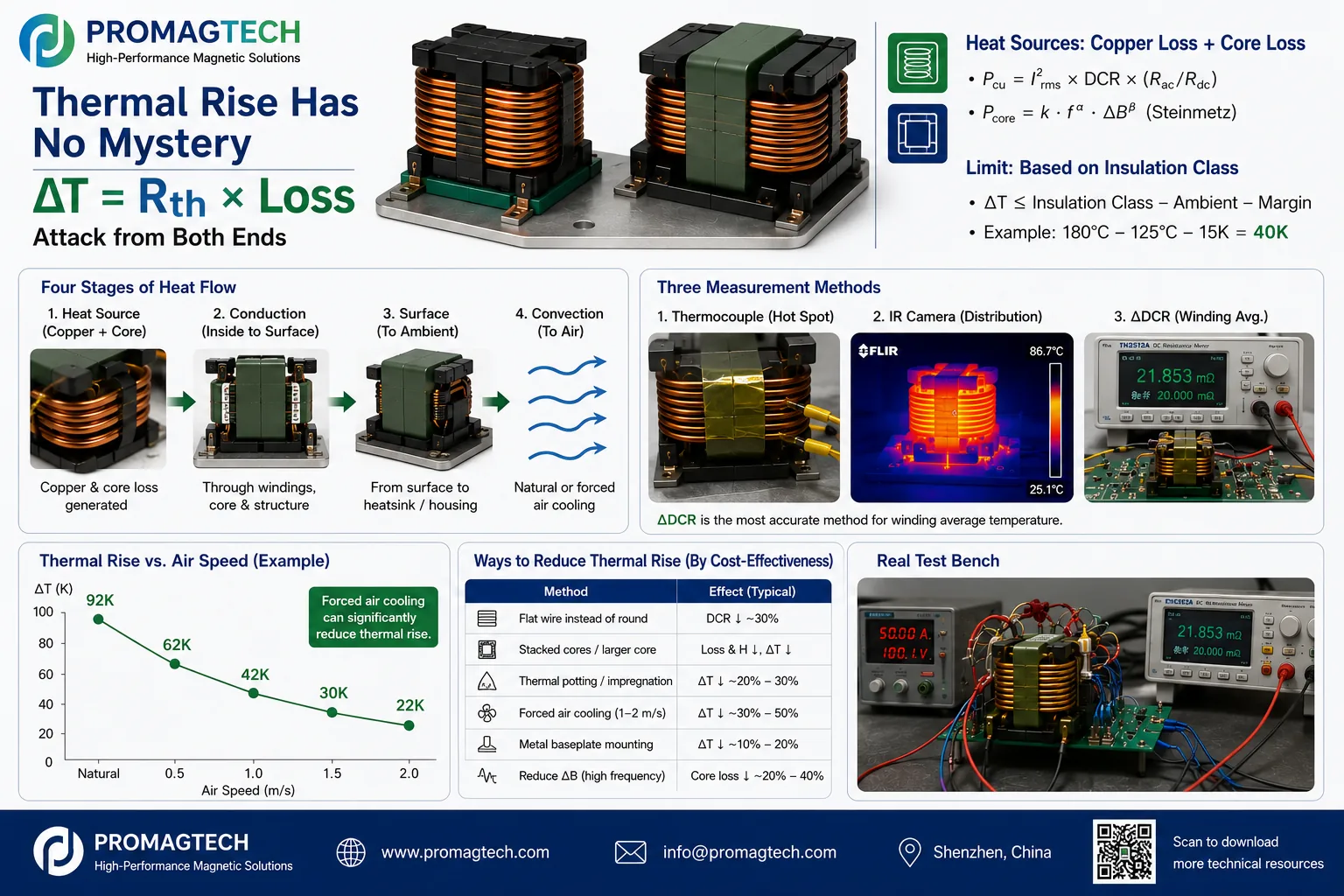
1. Thermal Model and Evidence Boundary
The guide expresses rise as ΔT ≈ Rth × (copper loss + core loss). Engineering has two levers: reduce the loss, or reduce total thermal resistance from winding to ambient. Every rise result must be tied to current waveform, frequency, ambient, airflow, mounting and the thermal-equilibrium criterion.
2. Start with a Loss Split
Copper loss includes I²R conduction loss plus high-frequency additions from skin and proximity effects. Core loss depends on material, frequency, flux-density swing and effective volume. Lower-frequency high-current PFC and storage applications are often copper-loss dominated; transformers operating from hundreds of kHz into the MHz range require both core-loss and AC-copper-loss control.
3. Thermal Path and Allowed Rise
Heat travels through the winding interior, core/bobbin/potting, external surface and finally the air. Derive the allowed rise from insulation thermal class - maximum ambient - design margin. The guide's example of 180°C insulation, 125°C ambient and 15K margin gives 40K; it demonstrates the method and is not a universal limit.
4. Use Three Measurement Methods Together
| Method | Measures | Boundary |
|---|---|---|
| Thermocouple | Contact hot spot | Measures only the attached point; lead routing may disturb the winding |
| IR camera | Surface temperature map | Needs emissivity calibration and does not directly represent the interior |
| ΔDCR method | Winding-average rise | Needs fast post-power measurement and extrapolation; does not replace hot-spot review |
For copper, the guide uses ΔT = (Rhot/Rcold - 1)/0.00393 to back out winding-average rise. It uses less than 1K change over 30 minutes as an example equilibrium criterion. A project report should also record ambient, airflow, mounting and measurement timing.
5. Cooling Levers and DVP Baseline
Low-DCR edge-wound flat wire, stacked or larger cores, thermal potting, forced air, metal-base conduction and lower ΔB can all improve thermal behavior. The PDF's roughly 30 percent and near-half improvements are illustrative, not guaranteed. A DVP baseline should cover loss split, ΔDCR average rise, hot spot, equilibrium, high-temperature operating life and batch spread.
6. Frequently Asked Questions
Should temperature rise be judged by average rise or hot spot?
Both. The ΔDCR method gives the winding-average rise that drives mean insulation ageing, while thermocouple and IR measurements identify the worst hot spot. Project acceptance criteria should address both values.
Why is my IR reading lower than the ΔDCR result?
IR measures the surface, while the winding interior can be hotter, especially in potted parts. IR alone can underestimate winding temperature, so it should be paired with the ΔDCR method.
How much can forced air reduce temperature rise?
As an illustrative order of magnitude, 1-2 m/s airflow can reduce rise to roughly half of natural cooling, but the result depends on structure and ducting. Airflow and ambient conditions must be fixed for comparable sample data.
How much can flat wire reduce temperature rise?
The guide uses about 30 percent lower DCR in the same winding window as an illustrative screening value. In a copper-loss-dominated high-current magnetic, copper loss may fall by a similar proportion, but the actual rise must be measured.
What is a typical temperature-rise limit?
There is no universal limit. Derive it from insulation thermal class minus maximum ambient temperature minus design margin. The guide notes that 40-65 K is common, with tighter limits in hot automotive environments.
Does thermal potting increase temperature rise?
Proper thermally conductive potting normally fills internal air gaps and reduces internal hot spots, although it can increase the time to thermal equilibrium. Material conductivity and coefficient-of-thermal-expansion compatibility still require review.
How does ProMagTech report temperature-rise data?
At the agreed current, frequency, airflow and ambient condition, ProMagTech can test with the ΔDCR method and hot-spot methods, then provide a report containing the loss split and thermal-equilibrium curve. Final acceptance remains project-specific.
Download the English PDF Guide
Seven-page English engineering guide, PMT-DOC-2026-0726-02, Rev A/0, dated 2026-07-26.
Download PDF Data