1. Why the Full Chain Matters
AI data center power density is pushing magnetic components into multiple conversion layers. A power architecture discussion that only reviews one transformer or one inductor can miss upstream insulation stress, intermediate bus current, downstream VRM ripple and EMI constraints.
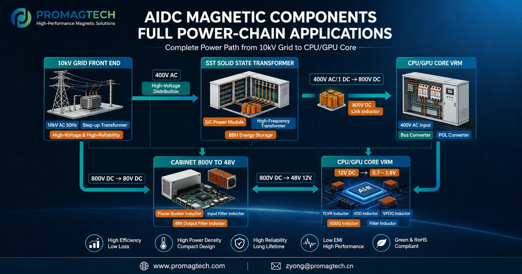
2. Magnetic Component Positions
High-voltage distribution and step-up or isolation stages require reliable transformer and high-voltage magnetic review.
Solid-state transformer systems can involve SiC power modules, high-frequency transformers, energy storage interfaces and DC-link inductors.
Busbar inductors, input filter inductors and 48V output filter inductors support high-current cabinet-level conversion.
TLVR, VDD, VDDQ and filter inductors must be reviewed against low-voltage, high-current transient requirements.
3. Engineering Review Points
Review each magnetic component against its real electrical position: voltage stress, RMS current, ripple current, peak current, switching frequency, cooling condition, insulation requirement, PCB or busbar interface, EMI filter function and validation plan.
The same label, such as "inductor" or "transformer", can mean very different design constraints across the chain. A high-voltage input magnetic, an 800V DC-link inductor and a processor VRM inductor should not be evaluated with the same checklist.
4. Evidence Boundary
The map is an application guide. It identifies where magnetic components are used and what engineering questions should be asked. Final specifications must be confirmed by the customer's topology, power level, voltage range, current waveform, thermal design, insulation standard and sample validation records.
Download the PDF Data Report
Download the English AIDC full power-chain magnetic components map for internal architecture review and supplier discussion.
Download PDF DataRelated Engineering Resources
48V AI server PSU flat transformer
Review EQ flat core and copper busbar transformer design in 48V AI server power supplies.
IBC DCX transformer loss analysis
Review magnetic loss in 48V to 12V intermediate-bus DCX transformer design.
High-current inductor design
Review saturation margin, DCR, material route and thermal structure for AIDC and PCS inductors.