1. Where the DCX Stage Sits
AI data-center power is moving toward higher-voltage distribution, but the 48V rail remains a key internal distribution voltage for IT loads. The IBC stage converts the 48V bus to a regulated or semi-regulated 12V bus for downstream POL or VRM stages. This makes the 48V to 12V DCX transformer a concentrated point for loss, thermal density and layout constraints.
2. Three Design Conclusions
In a fixed-ratio DCX stage, near-square-wave excitation can move the loss center from winding I²R loss toward core B-H hysteresis and eddy-current loss.
Sinusoidal Steinmetz estimation may under-estimate core loss when duty departs from 50% or when fast SiC/GaN edges concentrate flux change into a narrow time window.
For symmetric, small flux swing with little DC bias, low-loss MnZn ferrite can be more relevant than simply chasing high saturation flux density.
3. Product Boundary Shown in the Data Sheet
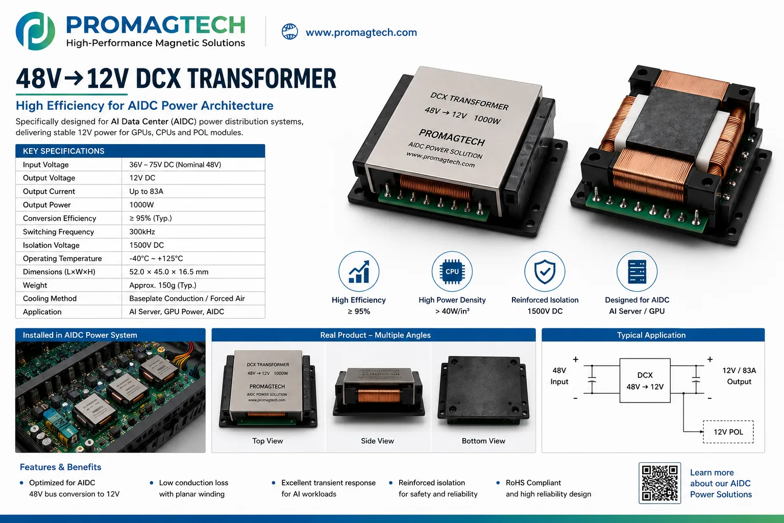
36V to 75V DC input, nominal 48V; 12V DC output; up to 83A output current; 1000W output power.
Typical conversion efficiency is listed as at least 95%, with 300kHz switching frequency in the public product sheet.
1500V DC isolation, -40°C to +125°C operating temperature range, baseplate conduction or forced-air cooling.
Designed for AI server, GPU power, AIDC power and 48V bus conversion to 12V intermediate rails.
4. Engineering Boundary
The values above are public engineering reference values from the supplied ProMagTech material. Final transformer selection still depends on topology, turns ratio, switching waveform, duty behavior, flux swing, thermal path, insulation requirement, PCB layout and validation data. For DCX loss analysis, the correct question is not only "what is the copper loss?" but "what waveform does the core actually see?"
Download the PDF Data Report
Download the English DCX transformer loss-analysis report for engineering review and supplier discussion.
Download PDF DataRelated Engineering Resources
Planar flat wire transformer
High-frequency transformer structures for compact isolated power conversion.
400kHz LLC transformer frequency knee
Review why the highest switching frequency is not always the best density point.
Magnetic integration
Review integrated transformer and resonant inductor design for LLC and DC-DC converters.