
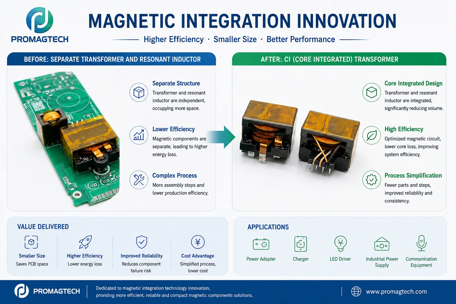
1. Why Magnetic Integration Matters
Power electronics are moving toward higher power density, smaller converter envelopes, and tighter thermal limits. In an LLC resonant converter or related isolated DC-DC converter, the high-frequency transformer and resonant inductor are often implemented as separate magnetic components. That approach is mature, easy to understand, and useful when design flexibility is more important than compactness.
The tradeoff is that separate magnetics can increase PCB footprint, component count, assembly operations, inventory complexity, and the number of thermal paths that must be controlled. Magnetic integration addresses this by engineering selected magnetic functions into one assembly, often called an integrated magnetic component or core integrated transformer.
2. Traditional Separate Magnetic Design
A conventional LLC converter magnetic set may include a high-frequency transformer, a discrete resonant inductor, and output filter components. The transformer handles energy transfer and isolation. The resonant inductor sets part of the resonant tank behavior. This separation can simplify early design tuning but adds more hardware to the power stage.
Input bus, output power, switching frequency, leakage inductance, resonant inductance, isolation and thermal path.
PCB area, magnetic part height, winding loss, core loss, assembly steps and heat dissipation.
Final design must be checked through sample measurement and converter-level testing, not only component-level calculation.
3. Core Integrated Transformer Design
In a core integrated transformer design, the transformer and resonant inductor functions are reviewed together. The magnetic circuit is arranged so that the required resonant inductance can be generated inside the transformer structure or coupled magnetic assembly. This can reduce the need for a separate resonant inductor when the converter requirements allow it.
For ProMagTech engineering review, the design discussion normally includes core geometry, material selection, winding structure, leakage inductance target, resonant inductance target, insulation system, terminal layout, thermal path, and manufacturability.
| Design item | How it should be reviewed |
|---|---|
| Power range | Confirm against topology, cooling method, frequency, insulation requirement and package size. |
| Switching frequency | Review core loss, AC copper loss, winding proximity effect and resonant tank behavior. |
| Resonant inductance | Define whether it can be integrated into the transformer structure or still requires a separate inductor. |
| Isolation voltage | Confirm creepage, clearance, insulation stack and hi-pot requirement from the approved specification. |
| Thermal performance | Validate winding temperature, core temperature, airflow, potting and PCB heat path in the real converter environment. |
4. Engineering Advantages When the Design Is Suitable
Reduced component count
Combining magnetic functions can reduce the number of discrete magnetic components in the converter. This can simplify purchasing, assembly, storage, inspection, and failure analysis. The practical benefit depends on the final design and production process.
Smaller magnetic footprint
When the magnetic circuit and winding layout are suitable, integration can help reduce total magnetic volume and free PCB area. This is valuable in compact power adapters, battery chargers, LED drivers, industrial power supplies, telecom power modules, and AI server power supplies.
Efficiency and thermal review
Integrated magnetic design may reduce duplicated core material, unnecessary winding paths, leakage flux issues, and assembly interfaces. However, efficiency improvement is not automatic. It must be proven through loss breakdown, thermal measurement, and converter-level efficiency testing.
Reliability and process simplification
Fewer parts and fewer assembly steps can reduce some process risks. At the same time, a more integrated structure can increase design complexity. That is why prototype validation, insulation review, production tooling review, and outgoing inspection planning are essential before mass production.
5. Typical Applications
- AI server power supplies: compact isolated DC-DC stages, high current density, and airflow-sensitive power modules.
- Telecom power systems: 48V power conversion, rectifier modules, and space-constrained power shelves.
- Battery chargers and power adapters: component-count reduction and simplified assembly for high-volume platforms.
- LED drivers: compact magnetic structures for isolated and resonant power stages.
- Renewable energy systems: solar inverter, energy storage and auxiliary power designs where magnetic volume and thermal control matter.
6. Buyer Checklist for a Custom Integrated Magnetic Review
- Converter topology: LLC, CLLC, flyback, forward, PSFB (phase-shifted full bridge) or another topology.
- Input voltage range, output voltage, output current and peak load condition.
- Switching frequency range and resonant tank target values.
- Transformer turns ratio, magnetizing inductance, leakage inductance and resonant inductance target.
- Isolation requirement, creepage and clearance requirement, insulation class and hi-pot test requirement.
- Mechanical envelope, terminal layout, PCB mounting method and airflow or potting condition.
- Expected sample quantity, annual volume, qualification documents and reliability test scope.
7. How ProMagTech Supports Magnetic Integration Projects
ProMagTech can review custom magnetic integration projects involving integrated transformers, resonant inductor integration, planar magnetics, flat wire transformers, high current inductors, PFC inductors and common mode chokes. The strongest engineering process starts with the real converter requirement, then moves through core selection, winding design, insulation stack, DCR target, thermal path, prototype sampling and project-specific testing.
For any quoted efficiency, size, cost or reliability improvement, the correct evidence is the approved drawing, sample test data, thermal image, OQC record and converter-level validation. Without those records, the value should remain a design target rather than a published guarantee.
Download the PDF Guide
Save this magnetic integration article as a PDF reference for internal design review or supplier discussion.
Download PDFRelated Engineering Resources
Planar flat wire transformer
Planar and flat-wire transformer assemblies for high-frequency resonant converters.
High power density flat wire magnetics white paper
Round-wire versus flat-wire trade-offs for window fill, AC loss, thermal path and production consistency.
Solar energy storage magnetics white paper
Magnetic component selection notes for PV inverters, storage PCS and bidirectional DC-DC stages.
Inductor and transformer design guides
Return to the technical resource library for related flat wire inductor and planar transformer design articles.
Request custom magnetic component review
Send converter topology, current waveform, frequency, voltage and mechanical limits for engineering review.
Frequently Asked Questions
What is the main engineering decision in Core Integrated Transformer vs Separate Magnetics?
The main decision is to match electrical stress, frequency, thermal path and mechanical envelope before confirming the magnetic component structure.
Which parameters should be provided for a custom review?
Provide input and output voltage, switching frequency, current waveform, target inductance or turns ratio, temperature limit, insulation requirement and mechanical drawing.
Can the values in this guide be used directly in production?
No. The values are design references. Production values should be confirmed through approved samples, DC bias checks, DCR measurement, hi-pot test and thermal validation.