
1. Anonymized Requirement and Evidence Boundary
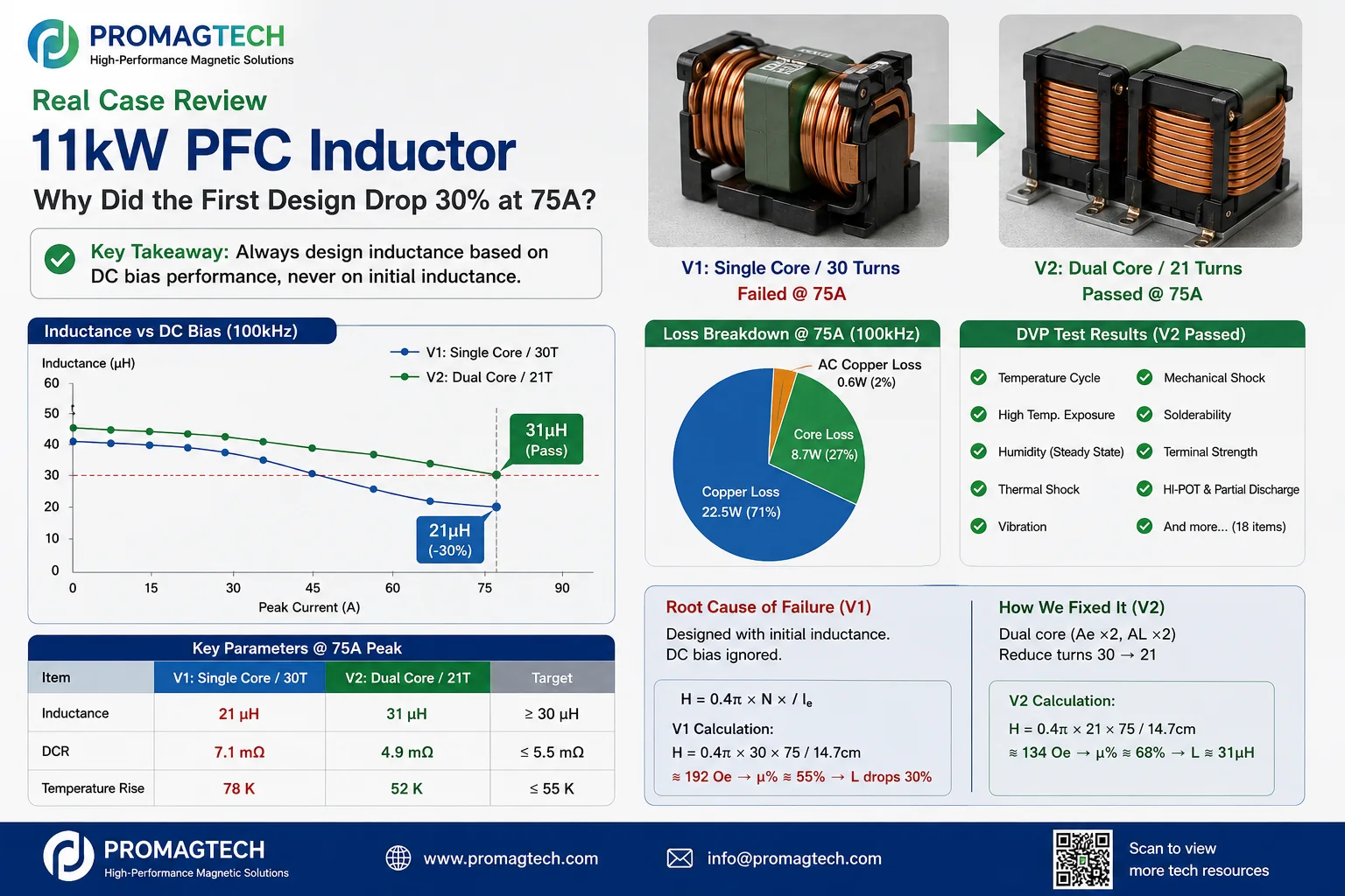
The PDF describes an 800V-platform OBC, single-phase totem-pole PFC, 11kW, 100kHz operating case with 50A rms / 75A peak current. Rounded targets include at least 42µH at 0A, at least 30µH at 75A peak, DCR no higher than 5.5mΩ, and temperature rise no higher than 55K at 50A rms.
2. Why the First Build Missed the Target
The first build used one Fe-Si powder core and 30 turns, with about 46µH estimated from initial AL. The PDF reports about 21µH measured at 75A peak, below the 30µH target. Its magnetic-path calculation gives about 192Oe, where the selected bias curve retained about 55% permeability. The design error was using initial inductance instead of loaded inductance to set turns.
3. Revision: Stack Cores, Reduce Turns and Lower H
The revision stacked two cores to increase effective area and AL, then reduced turns from 30 to 21. The PDF calculates about 134Oe and about 68% retained permeability, and reports 31µH at 75A peak. The edge-wound flat wire is listed as 5×1.6mm with reported DCR of 4.9mΩ.
4. Compare Losses at the Same Operating Point
The PDF text calculates losses at 50A rms / 100kHz: about 12.3W I²R copper loss, about 10W core loss and about 22W total, with reported temperature rise of 52K. The companion infographic labels a separate pie chart @75A and shows 22.5W, 8.7W and 0.6W. These are not the same operating point and must not be merged. Review the source current waveform, hot DCR, ΔB, loss curve and thermal record.
5. Sample Results Reported in the PDF
| Item | Anonymized reported value | Target |
|---|---|---|
| Inductance @ 0A | 46µH | ≥42µH |
| Inductance @ 75A peak | 31µH | ≥30µH |
| DCR | 4.9mΩ | ≤5.5mΩ |
| Temperature rise @ 50A rms | 52K | ≤55K |
| Hi-pot / partial discharge | Reported as pass | 800V reinforced-insulation requirement |
| Pilot-batch consistency | ±4% | <±7% |
6. Frequently Asked Questions
Why not just switch to High Flux?
High Flux can improve DC-bias capability, but it may increase material cost. In this anonymized case, stacked Fe-Si cores and fewer turns reduced operating field strength enough to meet the reported target. When space does not permit stacking, a more bias-tolerant material may be evaluated.
Are the values in this case real?
The PDF states that the values are anonymized and rounded while preserving the magnitude and engineering logic of the source project. They are not a universal specification and must be confirmed by project-specific sample tests and original records.
Does this method scale to other power levels?
The workflow scales: calculate operating field strength, read the selected core grade's DC-bias curve, correct effective permeability or AL, and set turns from loaded inductance. The numerical result must be recalculated for each power level, waveform, core and thermal design.
Can ProMagTech build a similar sample?
ProMagTech can review power, topology, current waveform, loaded-inductance target, DCR, temperature-rise limit, insulation and mechanical constraints, then propose a sample and validation plan. Delivery and pass criteria remain project-specific.
Download the English PDF Case
Download the 5-page English case. PDF revision EN-1.0 is dated 2026-07-16; the web page was published on 2026-07-24.
Download PDF Data