
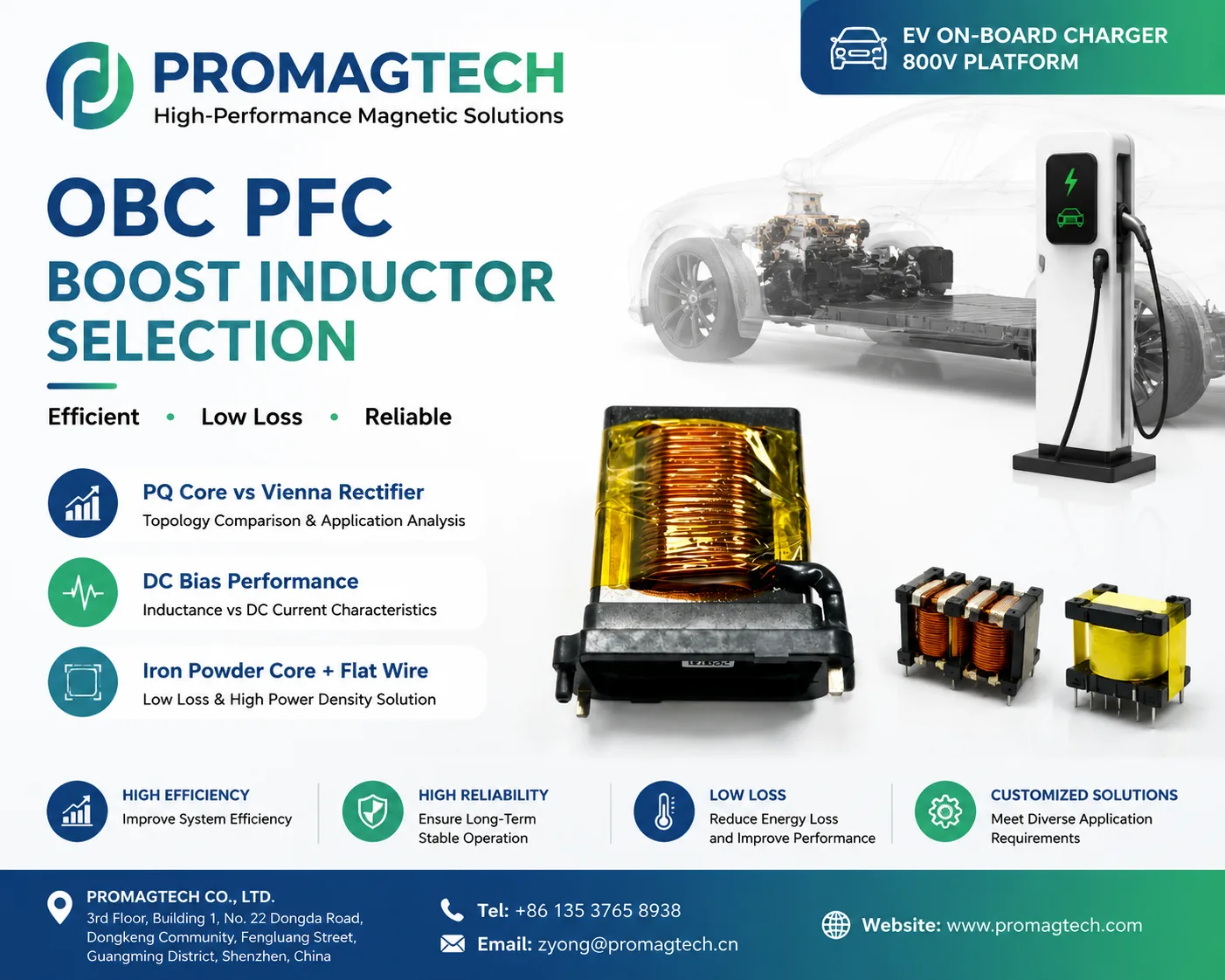
1. Where the PFC Boost Inductor Sits
The on-board charger rectifies grid AC into high-voltage DC for the battery. The PFC stage shapes the input current and boosts it to the DC bus. The boost inductor is the energy-storage and filtering element that directly affects efficiency, temperature rise and EMI behavior.
2. Topology Changes the Inductor Requirement
Single-phase design, one boost inductor, high single-phase current, fewer power legs and a cost-sensitive structure.
Three-phase design, one inductor per phase, balanced current sharing, lower ripple per phase and a better fit for higher power.
The supplied note lists 65-140kHz for GaN/SiC totem-pole operation and 65-100kHz for SiC Vienna operation.
Higher bus voltage raises insulation, creepage and partial-discharge review requirements.
3. Inductance Knee and DC Bias
PFC inductance is set by ripple current. Too little inductance raises ripple, peak current, EMI and core loss. Too much inductance adds turns, DCR, size and temperature rise. The practical point is the inductance knee, where ripple, copper loss, core loss and package size are balanced.
DC bias matters because the inductance rolls off with current. Powder cores provide soft saturation and usually hold inductance over a wider PFC current range, while hard-saturating gapped ferrite can drop sharply near the knee. The final route still depends on waveform, thermal limit, package and validation data.
4. Engineering Boundary
The figures and topology notes are public engineering reference data from the supplied ProMagTech material. Efficiency and temperature-rise values are design targets and must be confirmed through sample test data for each project.
Download the PDF Application Note
Download the English OBC PFC boost inductor application note for engineering review and supplier discussion.
Download PDF Data