AI data center infrastructure and energy storage PCS platforms are different applications, but their magnetic-component pressure points are similar: high current, compact layout, conversion efficiency, heat dissipation, and long-term reliability. A high-current inductor that is acceptable in a relaxed industrial power supply may fail in these platforms if saturation current, hot DCR, AC loss, and thermal path are not reviewed together.
For AIDC power, the inductor may sit in a 48 V bus DC/DC stage, POL/VRM support circuit, AI accelerator card power stage, server power module, or switch power architecture. For PCS, the inductor may support PV input stages, energy storage bidirectional conversion, DC bus filtering, or grid-connected conversion stages. The electrical environment differs, but the design discipline is the same.
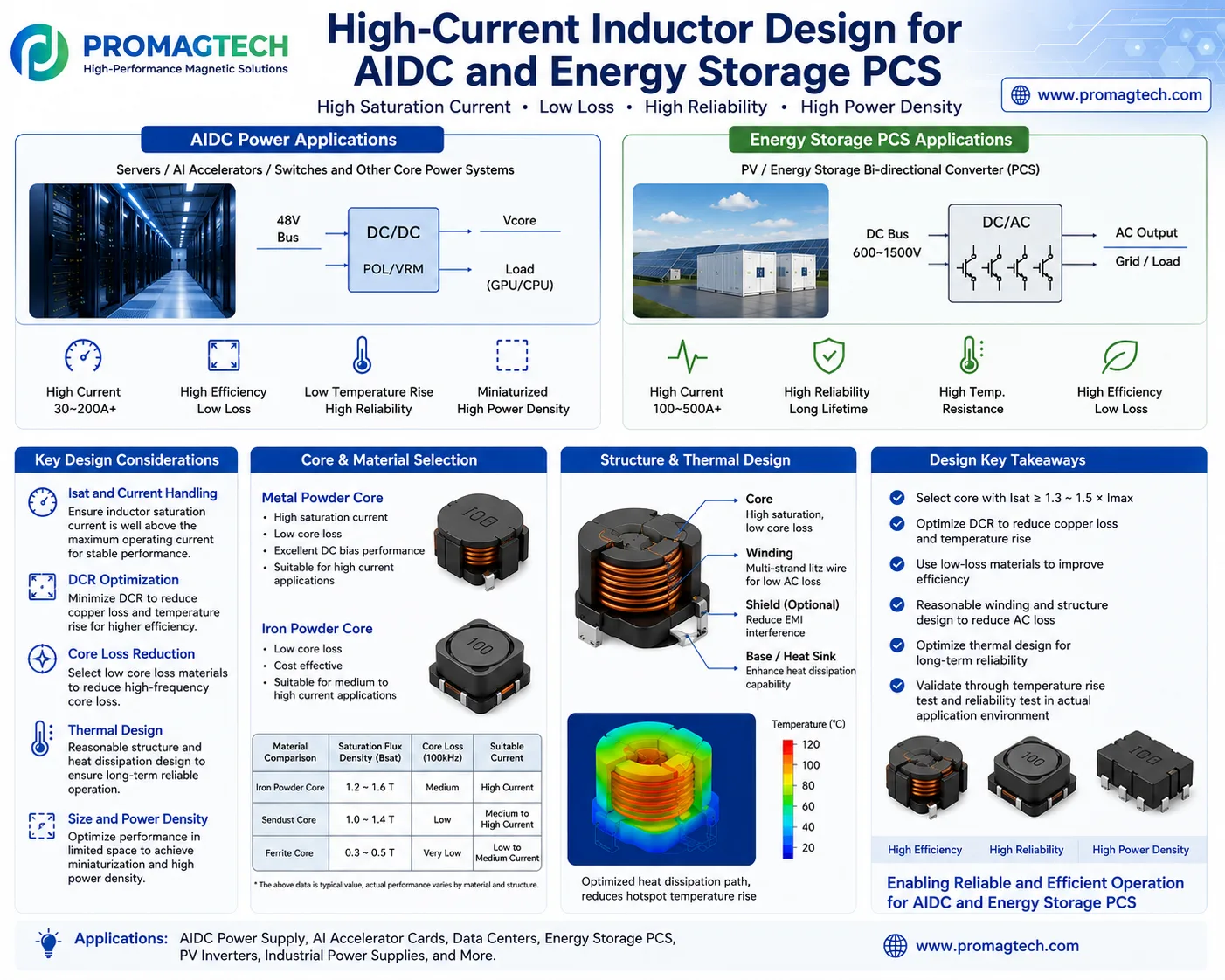
1. Application Context: AIDC vs. Energy Storage PCS
| Application | Typical power path | Inductor pressure points | Design risk |
|---|---|---|---|
| AIDC power systems | Server rack power, 48 V bus, DC/DC conversion, POL/VRM support, AI accelerator cards, switches, and core computing power modules. | High current, high efficiency, low temperature rise, compact height, and high power density. | Small thermal margin, dense PCB layout, airflow interaction, and high current transient behavior. |
| Energy storage PCS | PV or battery DC bus, bidirectional DC/DC conversion, DC/AC inverter stage, grid or load output. | High current, long operating life, high temperature resistance, low loss, and stable reliability under cycling. | Thermal cycling, current ripple, overload condition, insulation stress, and outdoor or cabinet-level heat buildup. |
2. Key Design Considerations
Set saturation current above maximum operating current with suitable margin. A common review target is roughly 1.3 to 1.5 times maximum current, but the exact margin depends on waveform, temperature, and fault condition.
Lower DCR reduces copper loss and temperature rise. Hot DCR should be reviewed, not only room-temperature DCR.
Core material must match frequency, ripple current, flux density swing, and operating temperature.
The magnetic design should include heat flow through winding, core, base, PCB copper, airflow, and optional heat sink path.
A smaller footprint is only useful if saturation, loss, insulation, and temperature rise remain inside the design limit.
3. Core and Material Selection
High-current inductors often use distributed-gap core materials because they can support DC bias more smoothly than a single discrete air-gap structure in many power designs. However, the best material is not fixed. It depends on current, frequency, ripple, loss target, package height, cost, and thermal structure.
| Material direction | Typical strength | Where it can fit | Engineering caution |
|---|---|---|---|
| Metal powder core | High saturation current, distributed air-gap behavior, and useful DC bias performance. | High-current AIDC power modules, PCS inductors, industrial power conversion, and compact high-current filtering. | Core loss and thermal rise must be checked at the actual switching frequency and ripple current. |
| Iron powder core | Cost-effective construction and suitability for some medium- to high-current applications. | Designs where cost, current handling, and package size must be balanced. | Loss, temperature, and efficiency may not fit every high-frequency platform. |
| Sendust or Fe-Si based core | Lower core loss than many traditional powder routes and useful medium-to-high-current capability. | PFC, DC/DC, inverter, and storage power conversion designs after project-specific review. | Saturation flux density, permeability, and loss curve must be matched to the waveform. |
| Ferrite core | Very low core loss in suitable high-frequency designs. | Lower- to medium-current designs or structures where an air gap and winding geometry can meet the current target. | Lower saturation flux density can make high-current DC bias design difficult without larger size or special structure. |
4. Structure and Thermal Design
High-current inductor design is a thermal design problem as much as a magnetic design problem. The core may provide saturation capability, but the winding and package determine whether the component can survive continuous current in the final enclosure.
- Core: Select for saturation margin, core loss, permeability stability, and operating temperature.
- Winding: Review flat wire, copper foil, multi-strand wire, or litz structures according to current density, AC loss, and manufacturability.
- Shield: Use shielding only when EMI or magnetic field containment requires it; shielding can also affect heat and parasitics.
- Base or heat sink path: Design a practical heat path from winding and core to PCB copper, airflow, enclosure, or heat sink.
5. AIDC Power Design Notes
AIDC power platforms often care about high current in a small space. The inductor must support high transient current without unacceptable saturation roll-off, while keeping DCR and AC loss low enough for dense thermal environments.
| Design area | What to check | Why it matters |
|---|---|---|
| 48 V bus conversion | Peak current, ripple current, saturation at hot condition, and winding temperature. | Small degradation can raise module temperature and reduce efficiency margin. |
| POL or VRM support | Transient current, footprint, height, and EMI interaction with nearby high-speed circuits. | Dense AI boards have limited space and limited thermal escape paths. |
| Server power modules | Airflow direction, hot-spot location, DCR, and repeatable manufacturing structure. | High-density racks punish components with inconsistent thermal behavior. |
6. Energy Storage PCS Design Notes
PCS inductors may face long operating hours, high DC bus voltage, bidirectional current, and cabinet-level thermal accumulation. The design must consider both steady-state current and operating cycles.
| Design area | What to check | Why it matters |
|---|---|---|
| DC bus and bidirectional conversion | Current direction, ripple current, saturation under overload, and loss at operating temperature. | PCS systems can operate continuously and often require long reliability margins. |
| PV and storage interface | Voltage stress, insulation spacing, environmental temperature, and thermal cycling. | Outdoor or cabinet installations can raise real component temperature above bench-test assumptions. |
| Grid or load output stage | Filter interaction, EMI, audible noise, and mechanical mounting. | Magnetic design must integrate with the complete inverter and filter structure. |
7. Validation Checklist Before Release
A drawing value is not enough for high-current applications. Before release, the inductor should be validated under the real electrical and thermal envelope.
- Inductance at rated current and hot condition.
- Saturation current margin versus maximum operating and fault current.
- DCR at room temperature and hot condition.
- Core loss and winding loss under actual switching frequency and ripple current.
- Temperature rise in the target enclosure, airflow, or heat sink configuration.
- Insulation, creepage, clearance, and voltage withstand according to project requirements.
- Mechanical fit, pin layout, vibration requirement, and assembly process.
- Reliability checks required by the end application, such as thermal cycling or long-duration load testing.
FAQ
Should the inductor saturation current always be 1.5 times the maximum current?
No. A 1.3 to 1.5 times margin is a useful review starting point, but the final target depends on operating temperature, transient current, protection strategy, ripple waveform, and acceptable inductance roll-off.
Does lower DCR always mean a better high-current inductor?
No. Lower DCR helps reduce conduction loss, but winding geometry can increase AC loss, size, cost, or parasitic effects. DCR must be optimized together with AC loss, core loss, thermal structure, and manufacturability.
Is a metal powder core better than ferrite for every AIDC or PCS design?
No. Metal powder cores are often strong candidates for high-current DC bias conditions, while ferrite may still be useful in suitable high-frequency or lower-current structures. Material choice must follow the real waveform and validation data.
How ProMagTech Supports High-Current Inductor Projects
SHENZHEN PROMAGTECH CO., LTD. develops custom high-current inductors, flat wire inductors, PFC inductors, energy storage magnetics, AIDC power magnetics, planar transformers, and related power magnetic components for industrial and high-power conversion applications.
For a practical review, send the converter topology, input/output voltage, inductance target, rated current, peak current, ripple current, switching frequency, allowed temperature rise, cooling method, size limit, mounting structure, and validation requirement.
Download the PDF Data Guide
Download the AIDC and energy storage PCS high-current inductor design PDF for internal design review and supplier discussion.
Download PDF Data