
1. Define the Architecture Boundary First: 48 V Is a Project Choice
NVIDIA's public material confirms an 800 VDC direction for future high-power AI racks and states that lower current can reduce copper requirements by about 45%. Public examples, however, include 800 V conversion to 54 V or 12 V and later high-ratio conversion directly to 12 V. This article therefore addresses magnetics selection when the project explicitly uses a 48 V intermediate bus; it does not present 800 V-to-48 V as a universal AIDC standard.
External architecture source: NVIDIA 800 VDC Technical Blog
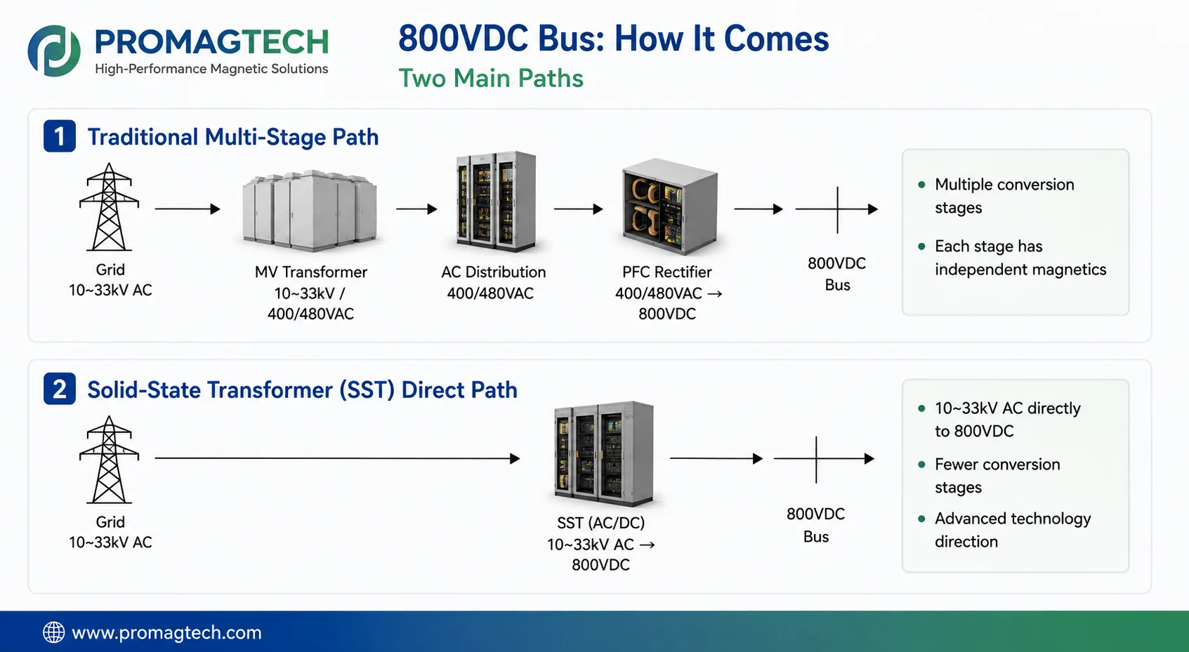
2. Two Paths to the 800 VDC Bus
| Path | Typical chain | Magnetics task |
|---|---|---|
| Conventional multi-stage | 10-33 kVAC → MV transformer → 400/480 VAC → PFC rectifier → 800 VDC | Line-frequency transformer, front-end PFC inductor and converter-stage magnetics. Industrial, PV and ESS front-end experience may extend here, but operating points still require recalculation. |
| SST direct path | 10-33 kVAC converted through power electronics directly to 800 VDC | Medium voltage, high frequency and high-voltage isolation add new insulation, PD, thermal and system-validation requirements; delivery scope is project-specific. |
3. Selecting the Isolation Step-Down for a 48 V Intermediate Bus
| Variable | Design tension | Review direction |
|---|---|---|
| Ratio and regulation | 800 V/48 V is about 16.7:1, but actual turns ratio depends on topology, duty cycle and rectification | Freeze input range, output range, power and resonant parameters before selecting turns and flux density |
| High secondary current | Low-voltage conduction and termination losses may dominate | Review synchronous rectification, flat wire or busbar, matrix paralleling and real termination resistance |
| Leakage and parasitics | Required resonant leakage trades against coupling and interwinding capacitance | Review Lm/Lr, leakage distribution, layer structure and EMI together |
| Power density | Parallel-module sharing, cooling and serviceability compete with volume | Planar or matrix structures are candidate directions, not performance claims without sample validation |
4. Division of Labor for PFC and Common-Mode Magnetics
In a conventional path, the PFC inductor controls ripple, current stress and loss; a bus-side common-mode choke targets the common-mode noise path and impedance band. Keep the physics separate: the winding carries full line current and its copper loss, but balanced conductor MMFs ideally cancel in the common-mode core. Core bias must be reviewed from imbalance, leakage coupling and fault conditions, not by applying full bus current directly to the core.
5. Minimum Project DVP
The DVP should include turns ratio, Lm/Lr and leakage, high-current secondary loss, delta-DCR temperature rise, infrared hot spots, parallel-module current sharing, common-mode impedance, insulation spacing and PDIV, plus efficiency from light to full load. Any illustrative target in the source document must be replaced by the project specification.
6. Frequently Asked Questions
Will 800 VDC architecture deploy at scale, or is it still conceptual?
NVIDIA has published an 800 VDC direction tied to future platforms, but implementations, downstream rails and standards are still evolving. Track NVIDIA, the Open Compute Project and the project specification rather than treating this article as a finalized customer architecture.
Can an 800 V-to-48 V isolation transformer directly reuse an EV 800 V OBC CLLC transformer?
Resonant-topology, Lm/Lr and insulation methods overlap, but output voltage, one-way or bidirectional operation, current sharing, power density and thermal boundaries differ. The structure requires project-specific adaptation; it is not a direct part-number reuse.
Is the bus-front-end inductor the same capability as an existing PV or ESS PFC inductor?
A 400/480 VAC front-end PFC in the conventional path is close to industrial or PV PFC-inductor methodology and may extend existing capability. An SST direct path adds medium-voltage, high-frequency and high-voltage-isolation requirements and cannot simply reuse an existing design.
How does an 800 VDC bus common-mode choke differ from an automotive 800 V common-mode choke?
Material and impedance-curve methods overlap, but winding current, insulation, temperature rise, parasitics, conductor imbalance and fault conditions require recalculation. Under balanced operation the two conductor MMFs ideally cancel, so full DC-bus current must not be treated as direct common-mode core bias.
Where does ProMagTech delivery capability end on this chain?
ProMagTech can focus on project evaluation of 800 V-to-48 V isolation transformers for architectures using a 48 V intermediate bus, including matrix or planar structures, plus bus-side common-mode magnetics. Grid-to-800 VDC sourcing, especially an SST path, requires project-specific review before delivery scope can be confirmed.
Download the English PDF Reference
Six-page English engineering reference, PMT-DOC-2026-0729-17, Rev A/0, dated 2026-07-29.
Download PDF Data