1. OBC PFC Role Boundary
The onboard charger handles AC charging, typically around 6.6kW, 11kW or 22kW. The PFC inductor challenge is not simply current magnitude. The harder problem is controlling loss, temperature rise and inductance retention in the smallest practical volume at the selected switching frequency and DC bias condition.
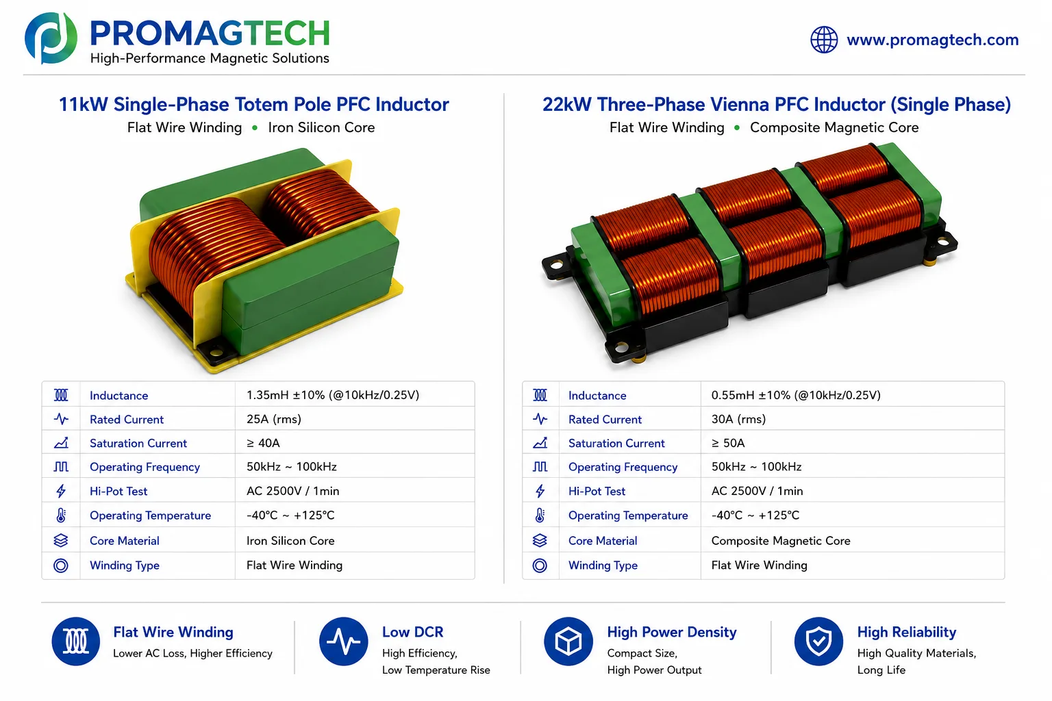
2. Topology Comparison
Flat wire winding, iron silicon core, 1.35mH ±10%, 25A rms rated current, saturation current at least 40A, 50kHz to 100kHz operating frequency.
Flat wire winding, composite magnetic core, 0.55mH ±10%, 30A rms rated current, saturation current at least 50A, 50kHz to 100kHz operating frequency.
3. What to Review First
Review inductance retention under peak current and DC bias before trusting no-load inductance.
At 65-140kHz, skin effect and proximity effect can drive temperature rise even when DCR looks acceptable.
FeSi powder core can be cost-effective for 11kW single-phase designs; heavier DC bias in 22kW three-phase designs may require High Flux or other material review.
Bench-level pass results can fail in sealed OBC environments if enclosure, airflow and mounting are not represented.
4. Engineering Boundary
The values shown here are public engineering reference values from the supplied ProMagTech material. Final PFC inductor selection must be confirmed by converter topology, switching frequency, ripple current, peak current, DC bias, core loss, winding AC loss, insulation requirement, cooling condition and validation data.
Download the PDF Data Report
Download the English OBC PFC inductor selection and design report for engineering review and supplier discussion.
Download PDF DataRelated Engineering Resources
PFC boost flat wire inductor
High-current PFC inductor structures for charging, industrial power and onboard charger designs.
20-60kW PFC inductor guide
Review ripple current, saturation margin and thermal design for high-power PFC inductors.
Flat wire inductor
Flat copper wire winding for low AC loss and compact thermal paths.