
1. Why 800 V Magnetics Need a Dedicated Insulation Review
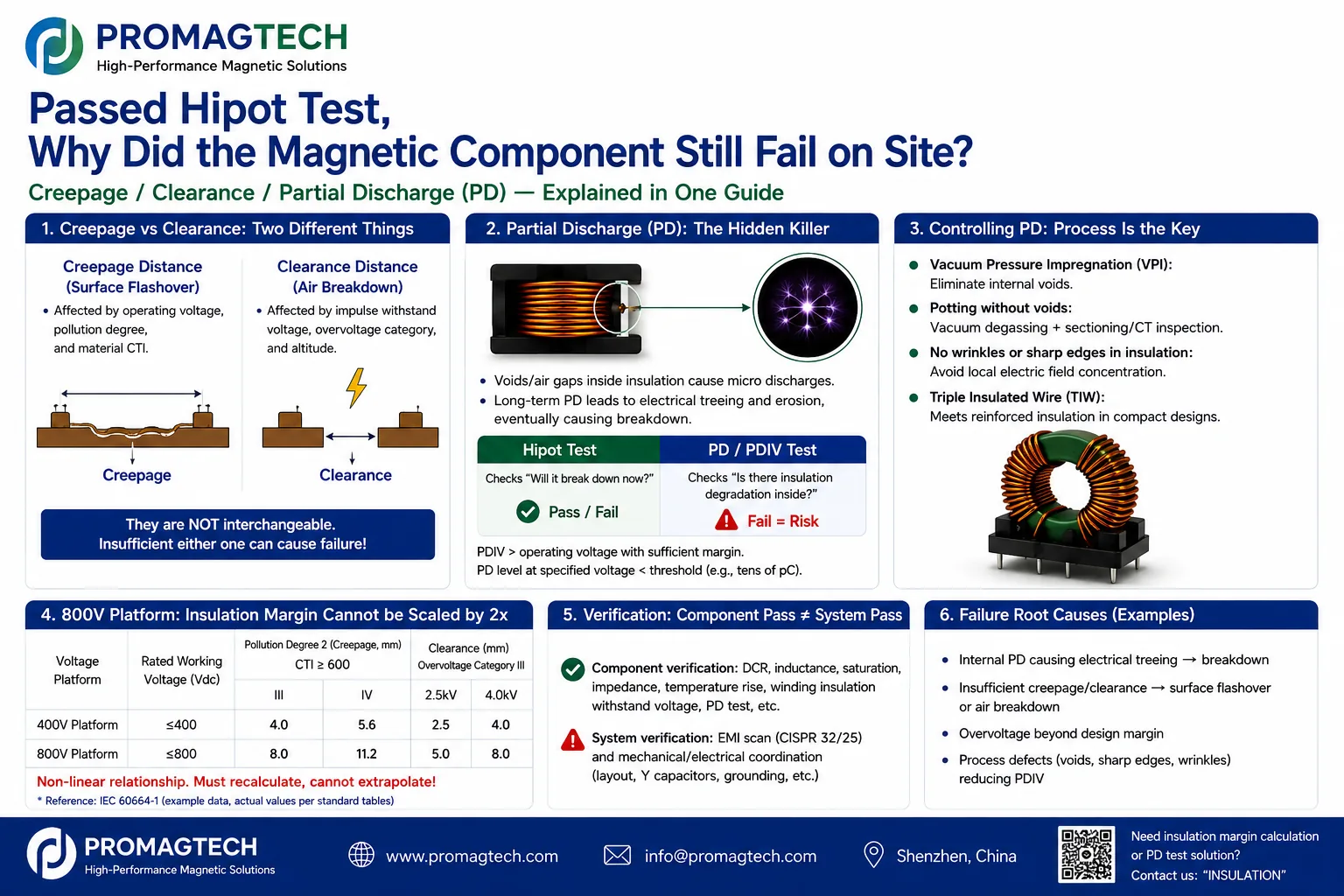
Moving from 400 V to 800 V does not permit insulation margins to be doubled mechanically. Clearance, creepage and partial discharge address air breakdown, surface tracking and internal micro-discharge respectively, with different design inputs and validation methods.
2. Clearance and Creepage Are Not Interchangeable
| Dimension | Clearance | Creepage |
|---|---|---|
| Failure controlled | Breakdown or arcing through air | Surface flashover or tracking |
| Main inputs | Impulse withstand, overvoltage category, altitude | Working voltage, pollution degree, material group/CTI |
| Reference framework | Relevant IEC 60664-1 tables | Relevant IEC 60664-1 tables |
| Common error | Ignoring high-altitude correction | Increasing air gap without checking the surface path and CTI |
3. Calculation and Structure Review Flow
Clearance: derive impulse withstand from system voltage and overvoltage category, look up the base clearance, then apply altitude correction where required. Creepage: use working voltage, pollution degree and material group; CTI for winding insulation, bobbin and potting material belongs in the design input. Ribs and grooves can extend the effective surface path, but the real structure must be measured.
4. Basic, Reinforced Insulation and Partial Discharge
The primary-to-secondary interface of an isolated CLLC or LLC transformer commonly crosses a safety-isolation boundary, but the system architecture and applicable product standard must set its insulation class. Hipot checks whether breakdown occurs during the test; insulation resistance measures a DC insulation level; partial-discharge testing evaluates PDIV and apparent charge at a specified voltage to reveal discharge at voids, bubbles or interfaces.
5. Process Control and DVP
Vacuum impregnation, degassed potting, wrinkle-free insulation, controlled edges, triple-insulated wire and suitable bobbin barriers may improve insulation stability, but they still require sample validation. The DVP should cover dimensional inspection, hipot, insulation resistance, PDIV or discharge magnitude, retest after thermal and humidity cycling, cross-section or CT sampling and batch consistency.
6. Frequently Asked Questions
We passed hipot. Why do we still need partial-discharge testing?
Hipot answers whether breakdown occurs during the test. It does not show whether voids or interfaces inside the insulation are already discharging. Repeated partial discharge can drive electrical treeing and erosion before a later field failure.
Why can clearance and creepage not substitute for each other?
They control different mechanisms. Clearance addresses arcing through air and depends on impulse withstand, overvoltage category and altitude. Creepage addresses surface flashover and depends on working voltage, pollution degree and material CTI. Both must be checked independently.
Can an 800 V design use twice the insulation margin of a 400 V design?
No. IEC 60664-1 lookup relationships are not linear, and partial-discharge risk does not scale linearly with voltage. The 800 V design must be recalculated from the applicable tables and product requirements.
What insulation class should an isolated CLLC or LLC transformer's primary-to-secondary interface use?
That interface normally crosses a safety-isolation boundary and often requires reinforced insulation or a basic-plus-supplementary double-insulation system. The applicable product standard and system safety architecture must set the final classification.
What partial-discharge acceptance threshold should be specified in pC?
There is no universal threshold. The discharge limit and test-voltage multiple depend on the applicable product standard, customer specification, insulation system and risk level. Illustrative values from another industry should not be copied into the project specification.
What changes for insulation design at high altitude?
Air dielectric strength decreases with altitude, so clearance commonly requires an altitude correction above the applicable reference elevation. Creepage is not directly corrected in the same way, but condensation and pollution degree still require reassessment.
What insulation and partial-discharge work can ProMagTech support?
ProMagTech can review project-specific clearance and creepage calculations, insulation structure, vacuum impregnation or void-control routes, and DVP items such as hipot, insulation resistance and PDIV or discharge magnitude. Final methods and acceptance criteria require agreement during design review.
Download the English PDF Reference
Eight-page English engineering reference, PMT-DOC-2026-0729-11, Rev A/0, dated 2026-07-29.
Download PDF Data