
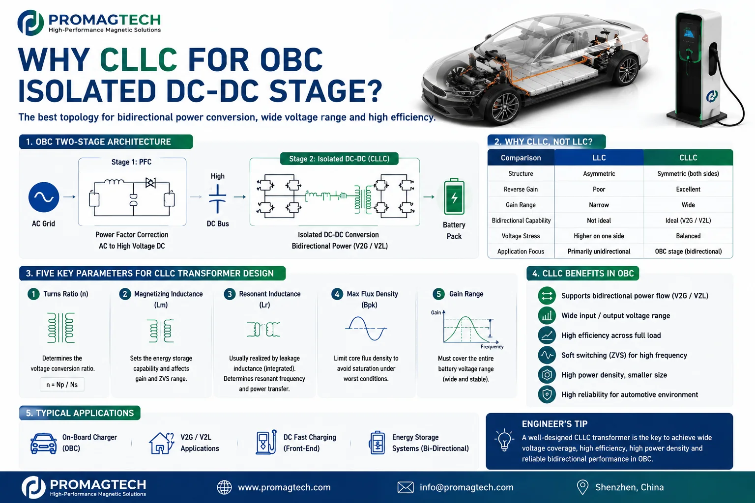
1. Where the CLLC Transformer Fits
In a typical 800V OBC, the PFC front end creates a high-voltage DC bus and the isolated rear stage converts energy between that bus and the battery. When V2G or V2L operation is required, the rear stage must support power flow in both directions. CLLC is one commonly evaluated resonant topology for this function.
2. Five Parameters Must Be Co-Designed
Set from the real bus and battery voltage windows, not a single nominal point.
Influences circulating current, ZVS margin and gain behavior.
May be discrete or implemented as controlled transformer leakage.
Must retain saturation margin over bidirectional waveforms and temperature.
Depends on Lm/Lr, Cr, frequency range, load and parasitics.
3. Winding, Insulation and Thermal Boundaries
Planar or flat-wire structures can provide repeatable geometry and a controlled thermal path, but they do not automatically guarantee low loss. Copper thickness, layer arrangement, proximity effect, interwinding capacitance, leakage symmetry, creepage and partial-discharge behavior must be reviewed together.
4. DVP Baseline Before Release
At sample stage, align measurement methods and acceptance limits for Lm, two-side leakage and symmetry, resonant frequency, Bpk margin, ZVS, bidirectional gain, efficiency, temperature rise, insulation resistance, hi-pot and partial discharge. Values shown in the PDF are design examples; project acceptance must come from the approved specification and test records.
5. Frequently Asked Questions
What exactly is the difference between CLLC and LLC?
LLC uses an asymmetric resonant tank optimized mainly for one-way conversion. CLLC adds a resonant branch on the secondary side, creating a more symmetric tank that can support forward and reverse power flow. Final topology selection still depends on gain range, control strategy and the operating envelope.
Why is the OBC rear stage increasingly bidirectional?
V2G and V2L functions require the isolated DC-DC stage to transfer power in both directions. CLLC is commonly evaluated for this role because its symmetric tank can support bidirectional gain, but efficiency must be confirmed over the actual voltage and load range.
Should the resonant inductor be integrated into the transformer?
The resonant inductance can be implemented as controlled transformer leakage to reduce component count and volume. This requires tighter winding and core control, and the forward and reverse leakage targets must be verified by samples.
How do I cover a wide battery voltage range?
The Lm-to-Lr ratio and operating-frequency range must be co-designed with the required gain window. A wider gain range can trade against light-load regulation, circulating current and efficiency, so it should be resolved at system-design stage.
Planar or wound transformer?
Planar construction can support low profile, repeatable geometry and controlled leakage at high frequency. Wound construction may suit high turns ratios or cost-sensitive designs. The choice depends on frequency, insulation, copper loss, thermal path, volume and production quantity.
What needs special care for 800 V isolation?
Review reinforced insulation, creepage, clearance and partial-discharge behavior between turns and layers. Hi-pot alone does not establish long-term insulation life; the project safety file and validation plan must define the final acceptance criteria.
Which is specified first, the transformer or the tank?
They should be specified together. Turns ratio, Lm and Lr interact directly with Cr, gain range, resonant frequency and ZVS behavior. Freezing the transformer independently can create system-level rework.
What can ProMagTech customize?
ProMagTech can review turns ratio, magnetizing inductance, integrated leakage and symmetry, flux-density margin, planar or flat-wire winding structure, insulation and partial-discharge scheme, height and temperature-rise targets. Final performance is established by the approved drawing, samples and DVP records.
Download the PDF Guide
Download the English 7-page selection guide for engineering review and supplier alignment.
Download PDF Data