Many EMI problems are misdiagnosed as a need for "more inductance." In common mode noise suppression, impedance across the relevant frequency band is usually more important than the nominal inductance value printed on a datasheet. A component with a high low-frequency inductance may still be weak at the actual noise frequency if the core material, winding capacitance, or self-resonant behavior does not match the system.
The practical selection flow is simple: identify the noise band, read the impedance curve, choose the core material, then verify current and thermal behavior in the real assembly.
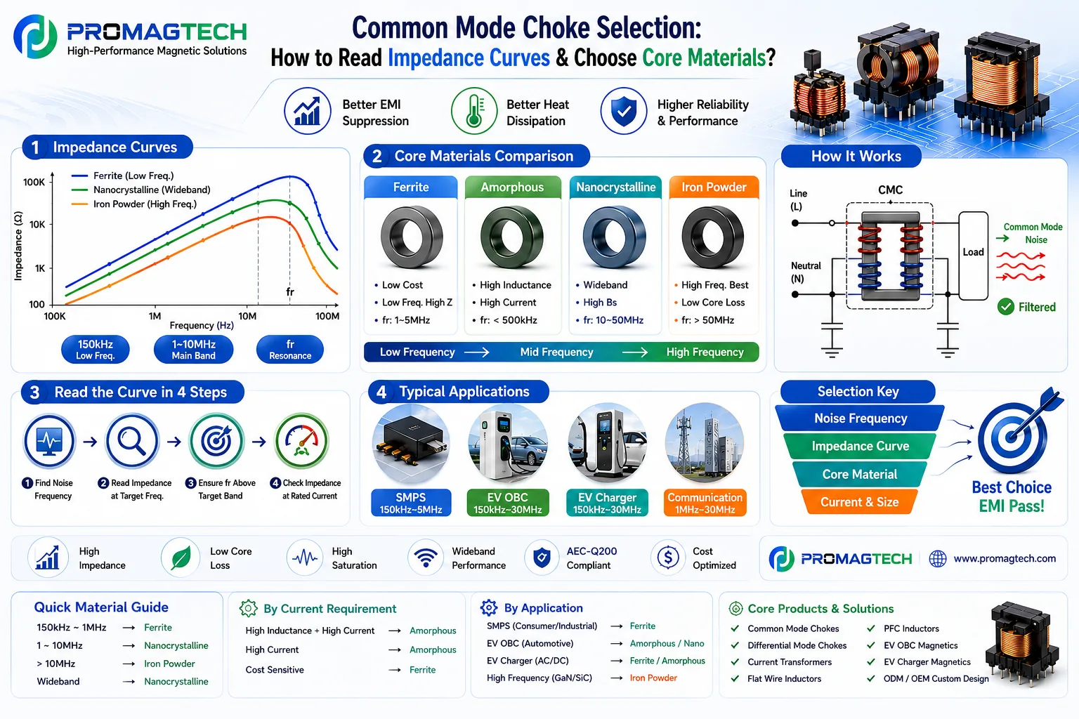
1. Start with Noise Frequency, Not Part Number
The impedance curve shows how strongly a common mode choke resists common mode current at each frequency. Before choosing a core, the engineer should locate the dominant noise band from conducted emission scans, oscilloscope measurements, or previous platform data.
| Noise range | Typical review focus | Selection risk |
|---|---|---|
| 150 kHz to 1 MHz | Low-frequency conducted EMI, input filters, SMPS and industrial power supplies. | A high-frequency optimized material may not provide enough impedance in this band. |
| 1 MHz to 10 MHz | Main EMI band for many switching converters, chargers, and compact power modules. | Core material, winding capacitance, and self-resonance must be checked together. |
| Above 10 MHz | Fast edges, GaN/SiC switching, cable radiation coupling, and high-frequency common mode paths. | A choke optimized only for low frequency can roll off before the target band. |
| Wideband noise | Systems with multiple switching nodes or long cable harnesses. | A single material may not cover the full band; two-stage or hybrid filtering may be needed. |
2. Read the Impedance Curve in Four Steps
Use EMI scan data or platform experience to identify the target band before choosing the choke.
Compare impedance where the noise actually appears, not only at the datasheet headline point.
The useful suppression band should not collapse before the required EMI band.
Confirm impedance retention, temperature rise, saturation margin, DCR, and insulation under operating current.
3. Compare Core Materials
Core material selection is the center of common mode choke design. The correct material depends on frequency, current, package size, temperature, cost, and qualification target.
| Core material | Typical strength | Common selection window | Main caution |
|---|---|---|---|
| Ferrite | Low cost and strong impedance in many low- to mid-frequency EMI filter designs. | Often reviewed around 150 kHz to several MHz, depending on grade and geometry. | Saturation, temperature behavior, and high-frequency roll-off must be checked. |
| Amorphous | High inductance and high-current capability for power filters requiring stronger current handling. | Often reviewed when high current and low-frequency common mode attenuation are important. | Core loss, mechanical size, and cost need project-specific review. |
| Nanocrystalline | Wideband impedance, high permeability, and strong performance potential in compact EMI filters. | Often reviewed for 1 MHz to tens of MHz noise bands and demanding power electronics filters. | Cost, supplier consistency, insulation, and process control should be confirmed. |
| Iron powder | High-frequency performance and lower core loss in selected high-frequency applications. | Often reviewed when noise extends above the range where ferrite or nanocrystalline designs are practical. | Do not use it as a default low-frequency common mode choke material without curve verification. |
4. Match Material to Application
Application context changes the selection priority. A charger, a server power supply, a communication power module, and an industrial SMPS may all need common mode suppression, but their current level, switching frequency, cable environment, safety requirements, and cost limits can be very different.
| Application | Typical noise band reference | Material direction to evaluate | Engineering check |
|---|---|---|---|
| SMPS and industrial power supplies | 150 kHz to 5 MHz | Ferrite is often the starting point. | Check impedance at the conducted EMI peaks, thermal rise, and filter interaction. |
| EV onboard charger | 150 kHz to 30 MHz | Amorphous and nanocrystalline options may be relevant, depending on current and bandwidth. | Check leakage path, insulation, safety spacing, common mode capacitance, and automotive documentation needs. |
| EV charger AC/DC stage | 150 kHz to 30 MHz | Ferrite, amorphous, or nanocrystalline should be compared by current and EMI band. | High current, heat, creepage, clearance, and line-frequency safety requirements are critical. |
| Communication power equipment | 1 MHz to 30 MHz | Nanocrystalline or other wideband solutions should be reviewed when compact broadband attenuation is required. | Confirm impedance after assembly and under real cable/grounding conditions. |
| High-frequency GaN/SiC platforms | Often above 10 MHz | Iron powder or specially selected high-frequency materials may need evaluation. | Fast dv/dt, parasitic capacitance, shielding, and PCB layout can dominate the final EMI result. |
5. Current, Size, and Heat Cannot Be Treated as Afterthoughts
A common mode choke that looks strong on an impedance curve can still fail in the real product if the winding DCR, copper temperature, insulation system, or core saturation margin is not suitable for the operating current. For high-current filters, the selection should include:
- Rated RMS current and overload condition.
- DCR, copper loss, and allowed temperature rise.
- Core material behavior at operating temperature.
- Impedance retention under current stress.
- Creepage, clearance, insulation class, and safety standard requirements.
- Available PCB footprint, height limit, pin layout, and assembly process.
6. When to Consider Two-Stage or Integrated Common Mode Chokes
If one choke cannot provide enough attenuation across the full band, a two-stage EMI filter may be more practical than oversizing a single component. Two-stage common mode chokes can split the suppression work across different winding structures, leakage behavior, and material choices.
For space-limited power systems, an integrated two-stage common mode choke can reduce component count and PCB area. The tradeoff is that the magnetic circuit, winding balance, leakage inductance, thermal behavior, and production consistency need a more disciplined design review.
Quick Material Guide
| Requirement | Material direction to review | Important warning |
|---|---|---|
| 150 kHz to 1 MHz EMI band | Ferrite | Verify current and temperature behavior in the final enclosure. |
| 1 MHz to 10 MHz main band | Nanocrystalline | Compare cost and supplier consistency before freezing the design. |
| Above 10 MHz | Iron powder or high-frequency optimized structures | Check that the choke does not add unwanted capacitance paths. |
| Wideband suppression | Nanocrystalline or two-stage filtering | Do not assume one impedance peak solves the full EMI scan. |
| High inductance plus high current | Amorphous | Review size, thermal rise, and cost against the full filter requirement. |
| Cost-sensitive filter | Ferrite | Make sure the low-cost material still covers the actual noise band. |
FAQ
Is a higher inductance common mode choke always better?
No. Higher inductance does not guarantee stronger attenuation at the target noise frequency. The impedance curve, self-resonant behavior, winding capacitance, current rating, and layout interaction are often more important.
Can a common mode choke alone guarantee EMI compliance?
No. EMI compliance depends on the full system: switching waveform, PCB layout, grounding, Y capacitors, shielding, cable routing, mechanical enclosure, and filter damping. The choke is one part of the solution.
Should automotive projects automatically use nanocrystalline cores?
No. Automotive power designs should select material by frequency band, current, temperature, package, cost, and required documentation. If AEC-Q200 or other automotive qualification evidence is required, it must be confirmed for the specific part and program.
How ProMagTech Supports EMI Filter Magnetics
SHENZHEN PROMAGTECH CO., LTD. develops custom common mode chokes, differential mode chokes, current transformers, flat wire inductors, PFC inductors, EV OBC magnetics, EV charger magnetics, and ODM/OEM magnetic components for industrial and vehicle-related power electronics applications.
For a practical common mode choke review, send the noise frequency band, rated current, line voltage, converter topology, available size, thermal target, insulation requirement, and any EMI scan data. This allows the magnetic component to be selected from engineering evidence instead of guesswork.
Download the PDF Data Guide
Download the 2026 common mode choke selection PDF for internal EMI filter review, supplier discussion, and engineering comparison.
Download PDF Data