
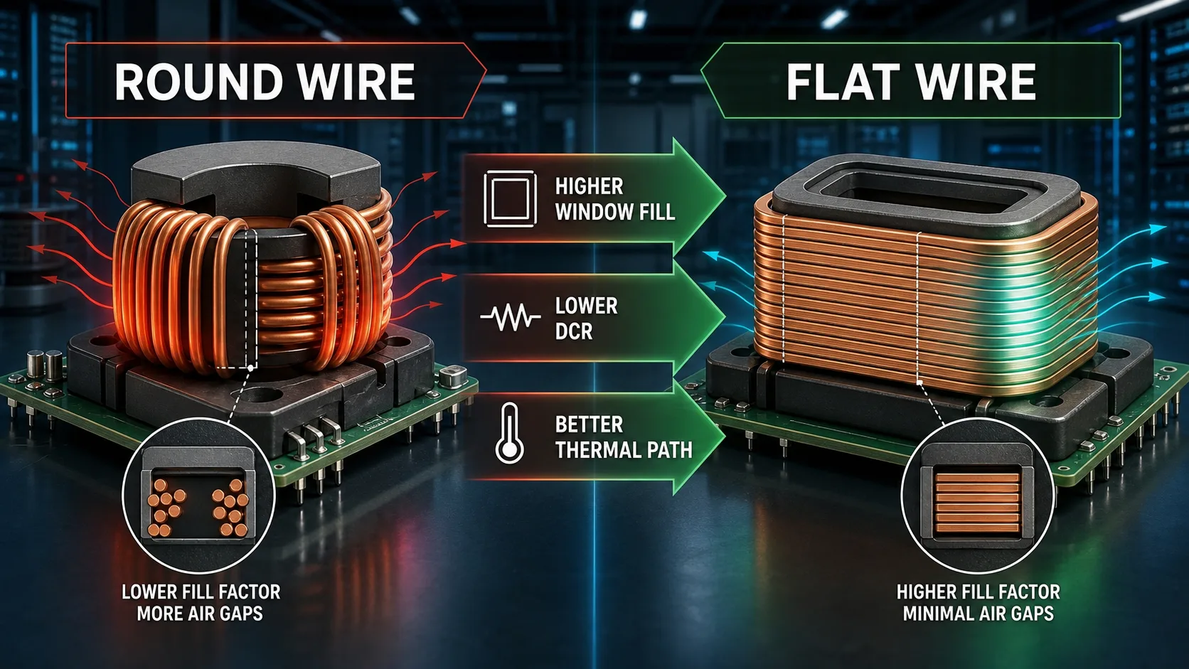
This ProMagTech white paper compares the engineering tradeoffs between traditional round-wire magnetic components and advanced flat-wire winding technology. The goal is not to claim that flat wire is always the correct answer; it is to show where geometry, thermal path, and automated winding consistency can change the design margin in high-current power electronics.
1. Round Wire vs Flat Wire: Core Engineering Differences
Window fill factor and Z-axis optimization
Round wire leaves unavoidable gaps because of its circular cross-section. In compact magnetic core windows, those gaps reduce usable copper area and often push the design toward a larger footprint or taller component.
Flat or rectangular copper wire can be stacked more compactly, improving window utilization and helping reduce Z-axis height or overall magnetic volume. This is especially valuable in ultra-thin inverter modules, EV charger power modules, and dense server power architectures where PCB area and airflow space are limited.
High-frequency AC loss and thermal management
At higher switching frequencies and high ripple current, round-wire windings are more exposed to skin effect and proximity effect. The result can be higher AC resistance, local heating, and reduced usable current margin.
Flat-wire designs provide a larger cooling surface and a shorter thermal path between copper, insulation, core, and ambient airflow. With the right winding geometry, insulation system, and core selection, this can reduce copper loss and improve temperature distribution. Final performance still depends on the converter frequency, ripple current, core material, airflow, potting, and mounting structure.
Production consistency and manufacturing throughput
Round-wire winding often depends on tension control and process discipline to keep batch variation under control. Flat-wire products are more compatible with automated winding, forming, and closed-loop process control, which helps reduce human-driven variation when the design has been validated for automated production.
Mechanical stability
For high-vibration or high-current assemblies, mechanical structure matters as much as the nominal inductance value. Flat-wire inductors with robust DIP pins, stable winding shape, and controlled fixing process can offer stronger assembly stability than heavy surface-mount structures in demanding environments.
2. Strategies for Breaking Power Density Bottlenecks
- Finite element analysis: Use electromagnetic simulation to review flux density, leakage, AC loss, and current ripple instead of relying only on legacy single-point calculations.
- Thermal network modeling: Treat winding loss, core loss, potting, airflow, PCB copper, and heatsink path as one thermal system.
- Magnetic integration: Where appropriate, combine transformer and inductor functions or optimize coupled magnetic structures to reduce total converter volume.
- Insulation and cooling synergy: Match insulation class, creepage and clearance, thermal gel, core slotting, forced air, or liquid-cooled structures to the actual voltage and ambient conditions.
3. Application Areas
48V power architecture, high-current conversion, localized thermal control, and EMI-sensitive layouts.
MPPT boost inductors, bidirectional DC-DC magnetics, low-loss operation, and outdoor thermal reliability.
PFC boost inductors, insulation margin, saturation current, vibration resistance, and sustained high-temperature operation.
4. Buyer Evaluation Checklist
- Rated current, saturation current, inductance tolerance, ripple current, and switching frequency.
- DCR and AC loss estimate under the real waveform, not only at room temperature DC conditions.
- Thermal rise target, cooling method, ambient temperature, potting method, and installation direction.
- Insulation class, voltage stress, creepage and clearance, and safety standard requirements.
- Mechanical fixing, pin design, vibration condition, and manufacturability at target production volume.
Conclusion
The move from round-wire winding to flat-wire and integrated magnetic structures is not just a styling change. It is a response to the physical limits of high-current, high-frequency power systems. When properly designed and validated, flat-wire technology can improve window utilization, thermal behavior, and production repeatability without treating inductance as the only design target.
For EV charging, solar inverter, energy storage, industrial power, and AI power architecture projects, ProMagTech can review custom magnetic component requirements around current, frequency, DCR, temperature rise, insulation, mounting, and validation evidence.
Download the PDF Data Guide
Download this ProMagTech engineering resource as a PDF for internal design review and supplier discussion.
Download PDF DataRelated Engineering Resources
High current flat wire inductor
Custom high-current flat wire inductors for EV, storage and industrial converters.
Planar flat wire transformer
Planar and flat-wire transformer assemblies for high-frequency resonant converters.
48V AI data center flat wire inductors
Thermal and winding-limit review for high-density 48V AI server power architectures.
Frequently Asked Questions
What is the main engineering decision in High Power Density Magnetic Components: From Round Wire to Flat Wire Technology?
The main decision is to match electrical stress, frequency, thermal path and mechanical envelope before confirming the magnetic component structure.
Which parameters should be provided for a custom review?
Provide input and output voltage, switching frequency, current waveform, target inductance or turns ratio, temperature limit, insulation requirement and mechanical drawing.
Can the values in this guide be used directly in production?
No. The values are design references. Production values should be confirmed through approved samples, DC bias checks, DCR measurement, hi-pot test and thermal validation.