
1. The architecture turns 800 VDC into a magnetics specification
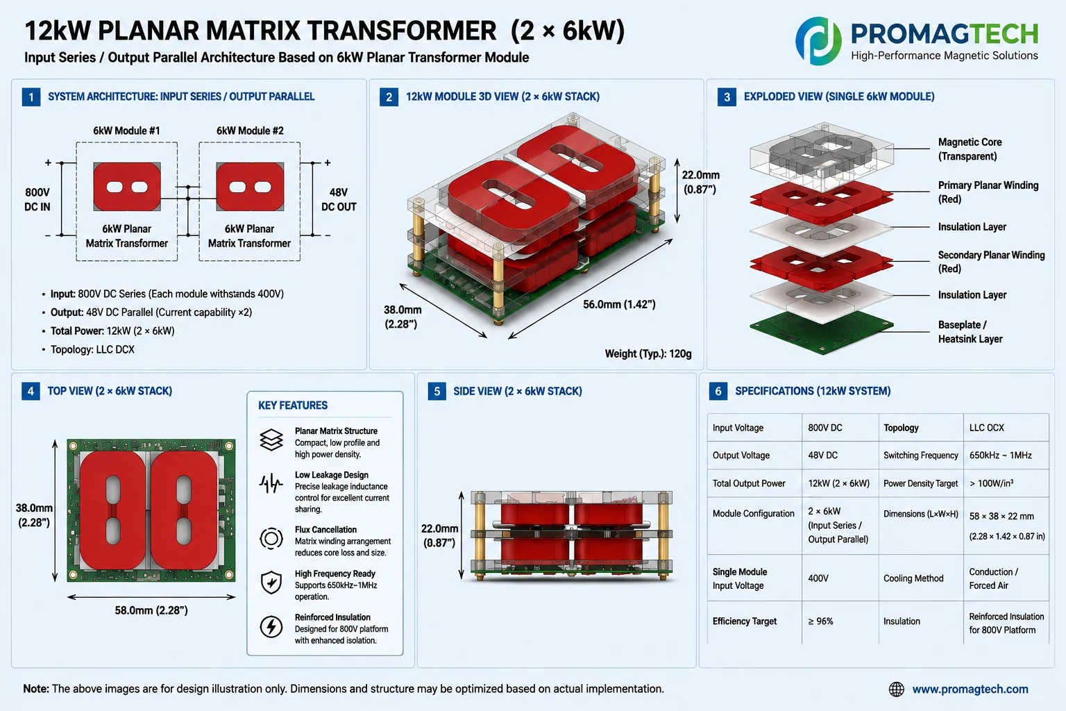
The paper positions an isolated 16:1 LLC DCX between an 800 V rack bus and the established 48 V ecosystem. Its cited direction—650 kHz to 1 MHz switching, modular 3 kW building blocks, series input and parallel output—makes transformer parasitics, phase matching and thermal geometry system-level parameters rather than component afterthoughts.
2. Why the planar matrix transformer is the enabling magnetic
A matrix transformer divides voltage and current across repeated cells while sharing magnetic structure. A planar implementation can shorten high-current paths and make interleaving repeatable. The useful comparison is not “planar versus wire-wound” in isolation; it is whether the selected matrix geometry can simultaneously control turns ratio, leakage, current sharing, insulation and heat flow.
3. Leakage matching controls current sharing
For paralleled output cells, phase-to-phase leakage mismatch changes each resonant path. The manufacturing target therefore cannot be only a low leakage-inductance value. It must include the allowed cell-to-cell spread, the measurement fixture and frequency, and the relationship between leakage, resonant current and synchronous-rectifier timing.
4. Equal airgap is a process-control problem
Local airgaps are affected by core flatness, spacer or adhesive thickness, clamping force and cure shrinkage. At 650 kHz to 1 MHz, a small local deviation can change reluctance, fringing field and nearby conductor loss. Gap definition, assembly sequence and lot-level verification belong in the drawing and control plan.
5. High frequency moves the loss boundary
Core selection must use the actual flux swing, waveform, frequency and temperature—not a room-temperature material headline. PCB copper thickness, layer count, interleaving and terminations determine AC resistance. Any quoted 98% DCX efficiency, greater-than-100 W/in³ power-density target or 58 × 38 × 22 mm illustration is a white-paper architecture target/reference, not a ProMagTech measured product result.
6. Isolation and thermal design cannot be separated
| Design item | Required engineering evidence |
|---|---|
| Reinforced isolation | Working voltage, overvoltage category, material group, altitude, creepage, clearance, dielectric construction, hipot and partial-discharge plan |
| Current sharing | Cell leakage distribution, winding and interconnect resistance, temperature coefficient and full-load sharing measurement |
| Thermal path | Copper/core loss split, hotspot location, interface material, airflow or cold-plate boundary and stabilized temperature-rise test |
| Production consistency | Gap control, winding stack registration, dimensional CTQs, electrical sampling plan and lot traceability |
7. The Vienna front end adds a separate inductor problem
The AC/DC front end still needs boost inductors capable of high DC bias, ripple-current loss control and predictable temperature rise. This is not the same optimization as the matrix transformer. Powder-core selection, turns, conductor geometry, magnetic stray field and cooling must be reviewed against the actual 20 kW-class front-end operating envelope.
8. Engineering review checklist
Before requesting a sample, define bus range, 48 V regulation window, power per cell, switching-frequency tolerance, resonant-tank targets, isolation standard, mechanical envelope, cooling boundary and DVP conditions. The supplier response should separate calculated targets, simulated results, sample measurements and production-release limits.
Renesas source: Power Architecture Evolution in Data Centers
9. Frequently Asked Questions
Is a matrix transformer the same as a planar transformer?
No. Planar describes the winding construction; matrix describes multiple transformer cells connected and magnetically integrated. The Renesas concept uses a planar-based matrix transformer.
Why is leakage matching more important than simply minimizing leakage?
In a parallel-output matrix structure, phase-to-phase leakage mismatch changes resonant impedance and current sharing. Low average leakage alone does not guarantee balanced cell current.
Why is equal-airgap control difficult in production?
Core flatness, adhesive thickness, clamping force and assembly tolerance perturb each local gap. At 650 kHz to 1 MHz, the resulting fringing and local loss can become significant.
What does 650 kHz to 1 MHz mean for core and winding design?
Material loss must be evaluated at the actual flux swing and temperature, while winding layer count, proximity loss, interconnect resistance and fringing exposure must be co-designed and measured.
Does this article prove ProMagTech can deliver the white-paper targets?
No. It is an independent technical teardown, not a Renesas endorsement, ProMagTech measurement report or production-performance guarantee. A project needs operating inputs, design review, samples and DVP evidence.
Download the Complete English PDF
PMT-DOC-2026-0823-30 · Rev A/0 · 10 pages · Published 2026-08-23.
Download PDF Data