A planar transformer is usually considered when low height, high power density, repeatable high-frequency behavior, and a clearer thermal path are important. A traditional transformer remains attractive when cost, design flexibility, fast prototyping, and a mature supply chain are the main priorities.
The better question is not which transformer is more advanced. The better question is which construction reduces project risk under the real operating conditions.
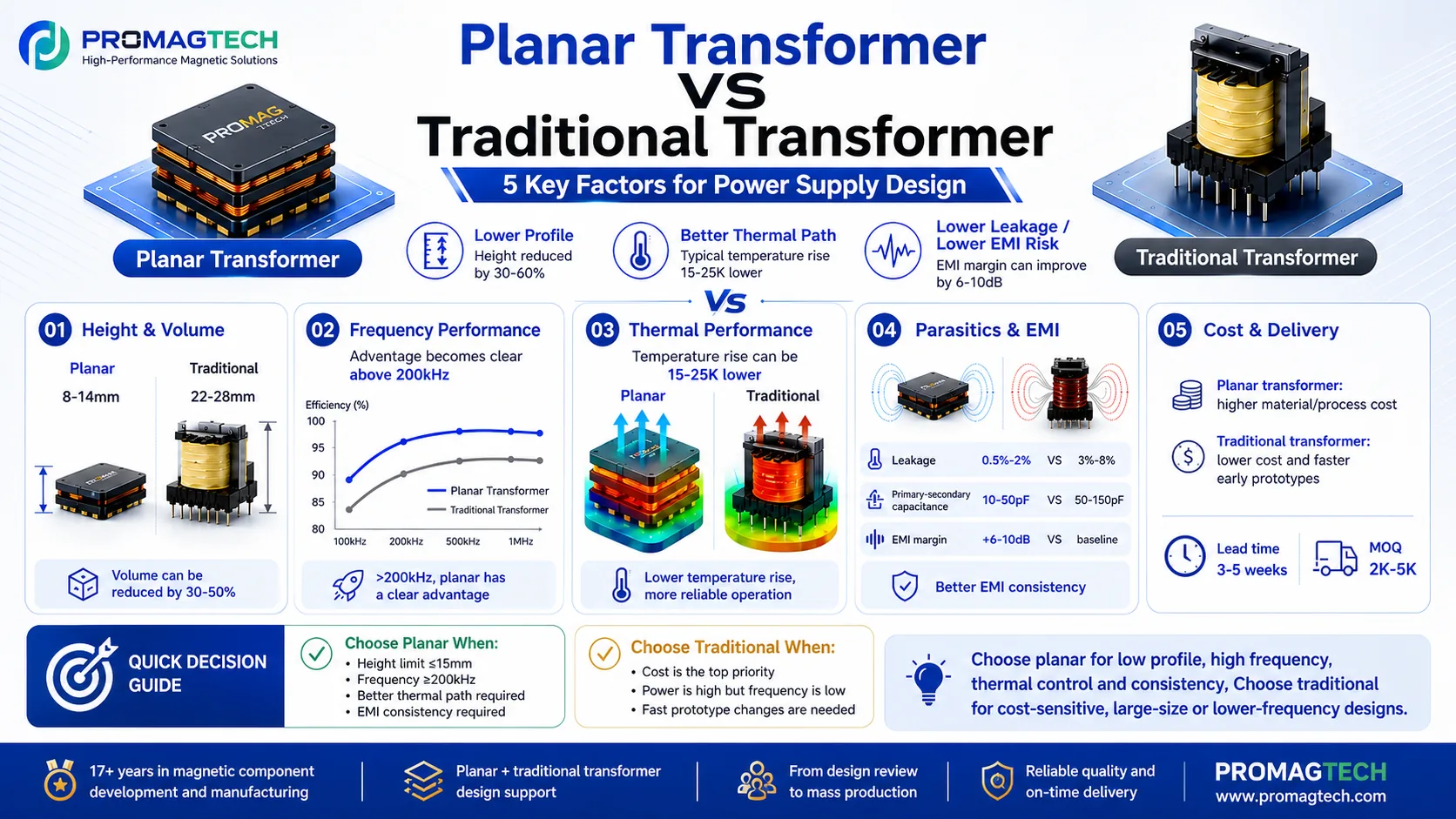
Quick Comparison
| Decision dimension | When planar becomes attractive | When traditional remains stronger |
|---|---|---|
| Height and volume | Low-profile packages, tight airflow paths, compact power modules, and high-density server power designs. | Products with relaxed height limits, simpler mechanical packaging, or cost-first requirements. |
| Switching frequency | Medium- to high-frequency converters where AC winding loss, leakage control, and repeatability become critical. | Lower-frequency platforms where wound construction can meet efficiency, temperature, and cost targets. |
| Thermal path | Designs that benefit from predictable heat spreading through copper layers, PCB interfaces, core contact surfaces, or heat sinks. | Applications where airflow and spacing are sufficient and hot-spot risk is manageable with conventional winding design. |
| EMI and parasitics | Projects requiring tighter control of leakage inductance, winding layout, interleaving, and repeatable parasitic behavior. | Projects where the existing transformer, layout, shielding, and filter network already pass EMI limits. |
| Production consistency | Programs that require stable repeatability across batches and lower dependence on manual winding variation. | Low-volume, early-stage, or frequently changing designs where hand-built prototypes can move faster. |
| Cost and schedule | Programs where system-level savings from height, cooling, assembly, or consistency can justify more front-end engineering. | Projects where unit price, tooling cost, and short sample lead time dominate the decision. |
1. Height and Volume
Planar transformers are often selected when magnetic component height affects the enclosure, airflow channel, heat sink, or PCB stacking strategy. In a compact power module, transformer height is not only a component dimension; it can decide the complete mechanical architecture.
A conventional transformer can still be the right choice when the product has enough vertical space and the design team values lower cost, faster winding changes, and a well-understood manufacturing process.
Engineering rule: if the allowed magnetic height is a hard constraint, evaluate planar construction early. If height is not a real constraint, do not choose planar only because it looks like a newer technology.
2. High-Frequency Behavior
At higher switching frequencies, skin effect and proximity effect increase AC winding loss. Traditional round wire, litz wire, and multi-strand constructions can manage these effects, but the result depends strongly on wire diameter, parallel paths, winding sequence, layer spacing, and process control.
Planar winding structures make it easier to define copper thickness, layer count, parallel current paths, interleaving, and shielding in a controlled stack-up. This can improve repeatability in LLC converters, server power supplies, and other high-frequency platforms, provided that distributed capacitance and insulation spacing are designed correctly.
| Frequency range | Typical evaluation direction | Main caution |
|---|---|---|
| Below 100 kHz | Traditional wound transformers are often cost-effective and flexible. | Do not add planar complexity unless height, thermal, or consistency targets require it. |
| 100-200 kHz | Both routes may be valid; compare loss, height, EMI, and total cost. | Prototype data matters more than a generic rule. |
| Above 200 kHz | Planar construction should usually be evaluated, especially for compact and repeatable designs. | Check interlayer capacitance, insulation system, and common-mode noise. |
| Above 500 kHz | Planar or other carefully controlled winding structures often become more relevant. | Magnetic material selection and loss modeling become critical. |
3. Thermal Design
A traditional transformer may place the hottest region inside the winding window or between insulation layers. Heat then travels through the winding, insulation, bobbin, air gap, and surrounding environment.
A planar transformer can offer a more direct path through copper layers, insulation interfaces, magnetic core surfaces, PCB copper, thermal pads, or a metal heat spreader. This does not mean every planar transformer runs cooler. Temperature rise depends on core material, copper loss, core loss, air gap design, assembly pressure, potting material, airflow, nearby heat sources, and final mechanical integration.
The honest engineering statement is that planar construction can make the thermal path more controllable, not that it automatically reduces temperature by a fixed number.
4. EMI, Leakage Inductance, and Parasitic Capacitance
EMI is not decided by the transformer alone. It is the combined result of switching nodes, current loop area, leakage inductance, winding capacitance, shielding, grounding, snubber design, and PCB layout.
Lower leakage inductance can reduce voltage spikes and snubber stress, but excessive interlayer capacitance may create a new common-mode noise path. Planar transformers are useful because winding geometry can be replicated more consistently. However, leakage, capacitance, and shielding strategy must be verified with waveform testing and EMI pre-compliance testing.
5. Production Consistency and Automation
Traditional transformer production depends on winding, taping, insulation assembly, core assembly, and operator experience. Mature suppliers can control these processes well, but design changes and batch-to-batch variation must still be managed.
Planar structures place more of the winding geometry into PCB, copper plate, stamped copper, laminated copper, or a hybrid stack. This can reduce dependence on manual winding variation and support more repeatable production once the design is stable.
| Project stage | Recommended bias | Reason |
|---|---|---|
| Early prototype with frequent parameter changes | Traditional transformer first, or a cautious planar feasibility study. | Fast iteration may matter more than final package optimization. |
| Specification mostly stable | Planar transformer becomes more practical. | Stack-up, tooling, insulation, and thermal interface can be optimized with fewer redesign loops. |
| Volume production with strict consistency target | Evaluate planar or other controlled winding structures. | Repeatability, assembly process, and test correlation become more valuable. |
6. Cost and Delivery Cycle
A traditional transformer often wins on sample speed, design flexibility, and direct component cost, especially when the design is still moving. A planar transformer may require more front-end engineering: stack-up design, insulation review, copper structure definition, tooling, thermal interface planning, and more prototype validation.
The correct cost comparison is not only transformer price. It should include heat sink size, PCB area, assembly steps, EMI debugging cost, failure risk, production consistency, and long-term supply stability.
Quick Decision Matrix
| Design condition | Planar transformer | Traditional transformer | Decision logic |
|---|---|---|---|
| Very low profile is required | Recommended to evaluate | Less attractive | Height and thermal path are strong drivers. |
| Switching frequency is high | Recommended to evaluate | Possible with careful winding design | AC loss, leakage, capacitance, and repeatability become more important. |
| Cost is the first constraint | Use only if system-level value is clear | Often preferred | Mature winding process is usually more economical. |
| Fast prototype iteration is needed | Use with caution | Often preferred | Design changes are usually faster with conventional winding. |
| Batch consistency is critical | Often preferred | Supplier-process dependent | Controlled winding geometry can improve repeatability. |
| EMI risk is high | Evaluate together with layout and shielding | Evaluate together with layout and shielding | Transformer structure alone cannot guarantee EMI performance. |
| Power level is above several kW | Needs full engineering review | Needs full engineering review | Topology, insulation, cooling, creepage, clearance, and magnetic material decide feasibility. |
FAQ
What power range can a planar transformer support?
There is no fixed universal limit. The feasible power range depends on topology, switching frequency, magnetic core size, copper thickness, cooling method, insulation requirement, temperature rise target, and mechanical size.
Does a planar transformer always use a PCB winding?
No. PCB winding is common because it offers good repeatability and clear layer definition, but planar transformers can also use copper foil, copper plate, stamped copper, laminated copper, or hybrid winding structures.
Is a planar transformer suitable for LLC converters?
Yes, but the design must treat leakage inductance, magnetizing inductance, distributed capacitance, winding loss, insulation, and EMI as one system. LLC converters are sensitive to resonant parameters, so the transformer should be developed together with the resonant tank, thermal design, and EMI strategy.
How ProMagTech Supports Custom Transformer Reviews
SHENZHEN PROMAGTECH CO., LTD. develops and manufactures custom magnetic components for power electronics applications, including planar transformers, high-frequency transformers, flat wire transformers, PFC inductors, flat wire inductors, and integrated magnetic solutions.
Typical engineering support includes parameter review, magnetic structure suggestion, prototype development, manufacturability review, and production consistency improvement. ProMagTech is especially focused on practical magnetic-component design for industrial power supplies, server power supplies, EV charging, energy storage, and high-frequency power conversion.
Send Transformer Parameters for Review