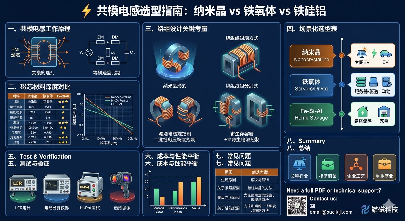
Common mode inductor (Common Mode Choke) is a key EMI suppression component, mainly used to suppress common mode interference. In switching power supplies, switching action generates common mode current that couples to ground through parasitic capacitance, forming conducted interference. Common mode inductors effectively attenuate conducted interference below 30MHz by increasing impedance in the common mode current path.
2. Core Material Selection
2.1 Ferrite
• High initial permeability (μi = 2000-10000)
• Low high-frequency loss
• Cost-effective
• Suitable for 100kHz-10MHz frequency band
• Disadvantage: low saturation flux density (Bs ≈ 0.4T)
2.2 Nanocrystalline
• High permeability (μi = 20000-80000)
• Good wideband characteristics
• Better saturation than ferrite
• Suitable for 30kHz-1MHz frequency band
• Higher cost
3. Magnetic Circuit Structure Design
3.1 Single Magnetic Circuit Structure
Two windings wound on the same core, differential mode current magnetic flux cancels out, common mode current magnetic flux adds up.
3.2 Winding Design Points
• Two windings must be tightly coupled, minimize leakage inductance
• Insulation between windings: withstand ≥1500VAC
• Recommend insulation class F (155°C) or above
4. Impedance Calculation
Common mode inductor impedance comes from:
• Complex permeability (μ' - jμ'') of core material
• Winding distributed capacitance
5. CISPR 32 Class B Design Points
To pass CISPR 32 Class B test, common mode inductor design must meet:
• Common mode impedance ≥200Ω at 150kHz
• Leakage current ≤3.5mA (for household equipment)
• Insulation resistance ≥10MΩ (500VDC test)
• Withstand voltage ≥1500VAC (between windings)
Download the PDF Data Guide
Download this ProMagTech engineering resource as a PDF for internal design review and supplier discussion.
Download PDF DataRelated Engineering Resources
Three-phase common mode inductor
Three-phase common mode chokes for inverter and storage converter EMI filtering.
High-frequency amorphous CM inductor
Amorphous-core EMI filter magnetics for SiC/GaN and compact power modules.
Two-stage integrated common mode choke
Integrated EMI choke design for EV chargers, AI server power, solar inverters and storage converters.
Frequently Asked Questions
What is the main engineering decision in Common Mode Inductor Design Guide: Improving EMI Performance?
The main decision is to match electrical stress, frequency, thermal path and mechanical envelope before confirming the magnetic component structure.
Which parameters should be provided for a custom review?
Provide input and output voltage, switching frequency, current waveform, target inductance or turns ratio, temperature limit, insulation requirement and mechanical drawing.
Can the values in this guide be used directly in production?
No. The values are design references. Production values should be confirmed through approved samples, DC bias checks, DCR measurement, hi-pot test and thermal validation.