
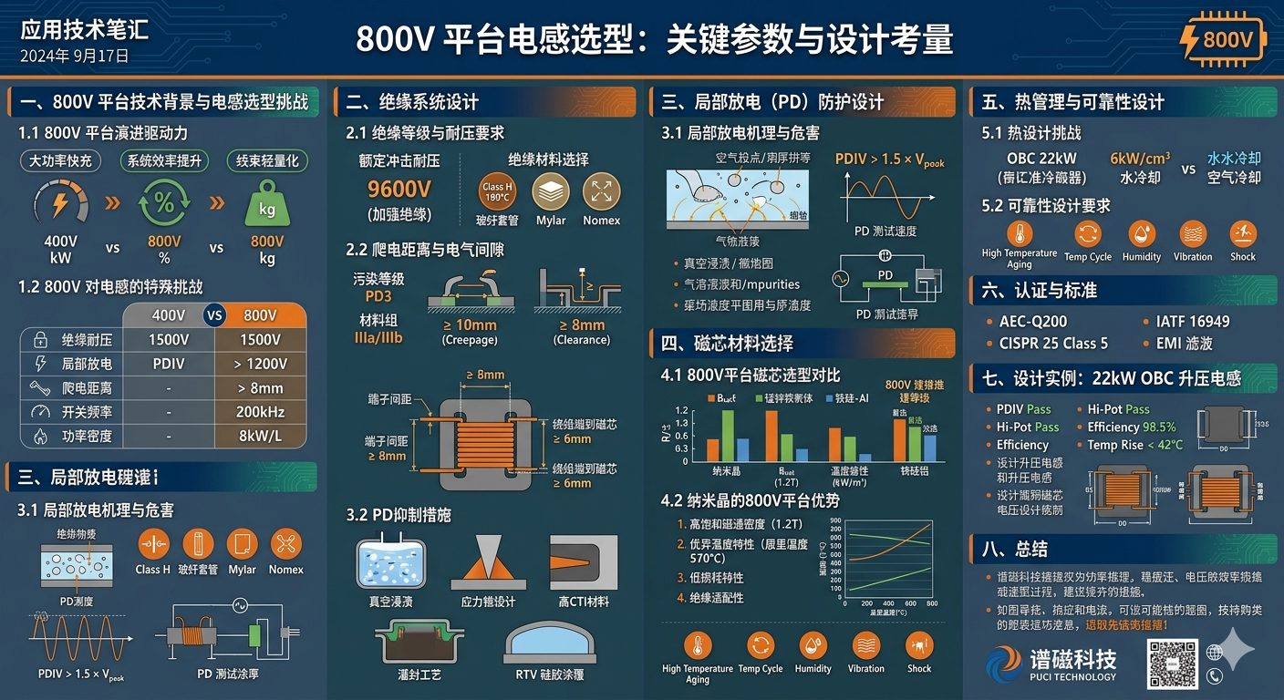
Inductor selection starts with the converter topology, normal and transient bus voltage, RMS current, peak current, ripple waveform, switching frequency range, ambient temperature, cooling path and mechanical envelope. An 800V-class system label alone is not enough to determine the magnetic design.
2. Coordinate insulation with the project safety file
Clearance, creepage, insulation system, dielectric withstand and partial-discharge criteria must be derived from the applicable product standard and the project's working voltage, overvoltage category, pollution degree, material group, altitude and insulation classification. This page does not prescribe universal spacing or test limits.
3. Review magnetic and thermal margins together
Core material and winding geometry are evaluated against DC-bias behavior, flux swing, copper loss, core loss and the agreed cooling condition. Frequency ranges associated with SiC switching devices are project inputs, not guaranteed operating ranges for every inductor.
4. Validation evidence required before release
Final values are tied to the approved drawing and sample record. The validation plan should define inductance and DCR conditions, DC-bias checks, dielectric and partial-discharge tests where applicable, temperature-rise conditions and system-level verification.
Download the PDF Data Guide
Download this ProMagTech engineering resource as a PDF for internal design review and supplier discussion.
Download PDF DataRelated Engineering Resources
Charging station PFC inductor
PFC inductors for 20-60kW EV DC charging station power modules.
PFC boost flat wire inductor
Flat wire boost inductors for single-phase and three-phase PFC circuits.
20-60kW PFC inductor design guide
Selection and calculation notes for charging-station and industrial three-phase PFC inductors.
Frequently Asked Questions
What is the main engineering decision in 800V Platform Inductor Selection: EV High Voltage Solutions?
The main decision is to match electrical stress, frequency, thermal path and mechanical envelope before confirming the magnetic component structure.
Which parameters should be provided for a custom review?
Provide input and output voltage, switching frequency, current waveform, target inductance or turns ratio, temperature limit, insulation requirement and mechanical drawing.
Can the values in this guide be used directly in production?
No. The values are design references. Production values should be confirmed through approved samples, DC bias checks, DCR measurement, hi-pot test and thermal validation.