
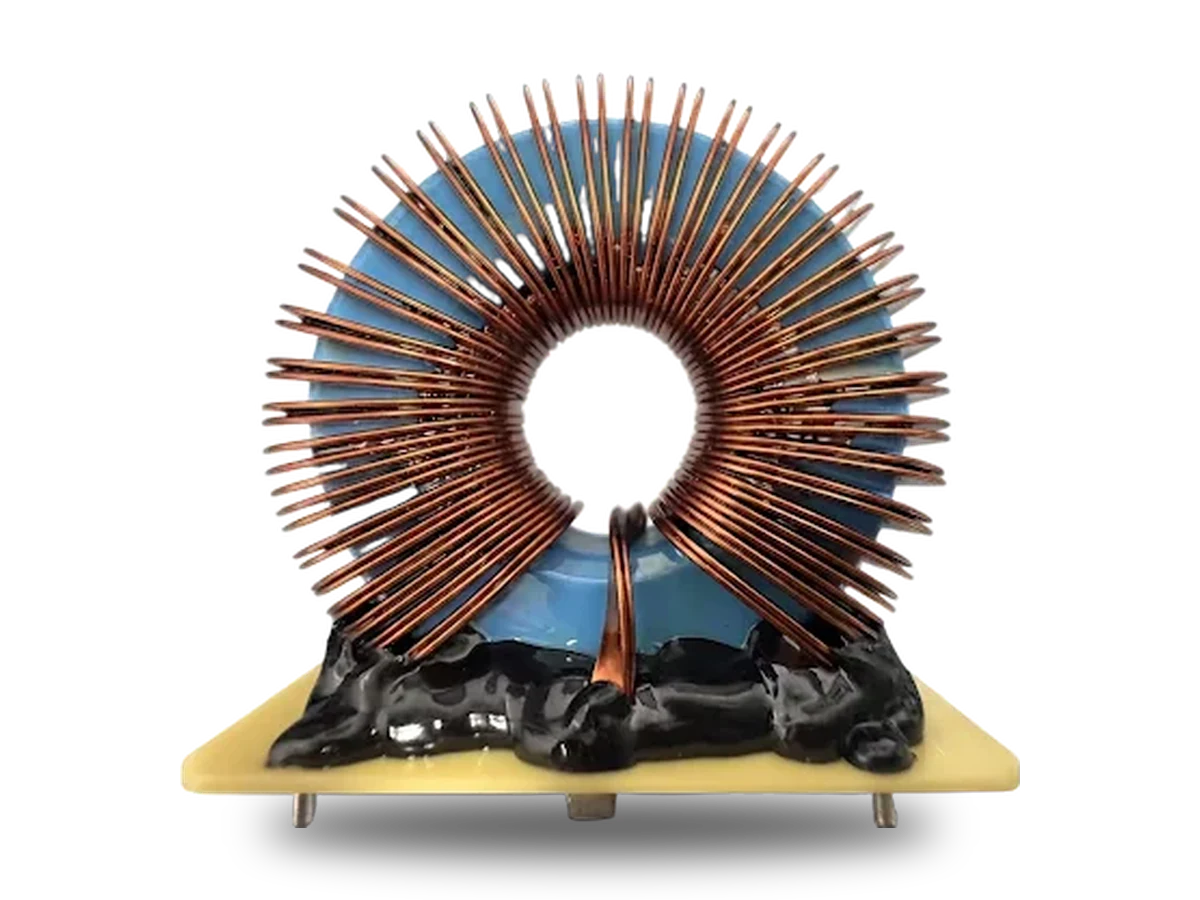
This product page records the values shown in the supplied design sheet. The inductor uses two NPC250060 magnetic cores and a two-parallel flat-copper winding on a PCB-mounted structure. It is presented as a custom design reference, not as an unconditional off-the-shelf specification for every converter.
Electrical and Mechanical Data
| Parameter | Published value | Interpretation |
|---|---|---|
| Nominal inductance | 500 µH | 497.66 µH measured at 0 A |
| Rated current | 50 A | Rated-current value stated on the supplied sheet |
| Average-current evaluation point | 65 A | Separate test/design condition; not relabeled as rated current |
| L@65 A | 130.25 µH | Published DC-bias result at H = 204.624 Oe |
| Peak-current evaluation point | 91.92 A | Published peak-current condition |
| [email protected] A | 68.24 µH | Published DC-bias result at H = 289.370 Oe |
| Ripple current | 18.38 A | Waveform convention should be confirmed for the target converter |
| DC resistance | 15.79 mΩ | Conductor temperature and measurement method were not supplied separately |
| Reference frequency | 10 kHz | Published test/design condition |
| Core structure | 2 × NPC250060 | High-performance magnetic core, dual-toroid arrangement |
| Winding | T0.8 × 4 × 2P, 36 turns | Flat copper wire, two parallel conductors |
| Copper weight | 337.23 g | Published winding value |
| Mounting | PCB mount | 72 × 62 × 69 mm overall envelope |
| Operating temperature | -40°C to +125°C | Final system qualification remains project-specific |
Current-Rating Boundary
50 A is the published rated-current value. The same source sheet lists 65 A as an average-current evaluation condition and 91.92 A as a peak-current point. This page keeps those labels separate and does not claim that the component maintains 500 µH at either high-current point.
Published Loss Reference
At the 65 A evaluation condition, the supplied sheet reports 0.080 W core loss, 66.70 W copper loss and 66.78 W total loss. The copper-loss value is consistent with I²R using 65 A and 15.79 mΩ. Temperature rise, airflow, conductor hot resistance and thermal equilibrium data are not included in the supplied material and must be validated on the project sample.
Product Specification Image

Application Review
The published application scope includes energy-storage systems, battery-management power stages, DC/DC converters, inverters and industrial power electronics. For a new design, provide the exact topology, DC bus voltage, switching frequency, RMS and peak current, ripple definition, inductance target under DC bias, cooling condition, insulation requirement and installation envelope.
Send Parameters for Engineering ReviewFrequently Asked Questions
Is 65 A the rated current?
No. The supplied sheet states 50 A rated current. The 65 A value is a separate average-current evaluation condition.
Does the inductor maintain 500 µH at 65 A?
No. The published values are 497.66 µH at 0 A, 130.25 µH at 65 A and 68.24 µH at 91.92 A.
Is the approximately 35% harmonic-suppression value universal?
No. It is retained as a source-sheet reference. System harmonic performance depends on topology, control, operating point, layout and validation conditions.